This thread has been locked.

If you have a related question, please click the "Ask a related question" button in the top right corner. The newly created question will be automatically linked to this question.

TMS320DM8127: 12-bit Bayer data input from sensor ==> 8 bit YUV420 data output to Camera Link - How is this done?

Part Number: TMS320DM8127
Other Parts Discussed in Thread: DM385

Hi,

IPNC_RDK 3.8.0 - using AR0331 sensor.

HDR images are output from the sensor and captured using the DCC tool in BAYER 12-bit format.

The images that enter the Camera link are YUV420 - 8-bit.

  • I'm interested in knowing which LUT or gamma is used when converting the 12-bit to 8-bit images? Or are 4 LSB bits just ignored?
  • Where is the conversion done?

Thanks,

Mechi

  • Hi Mechi,

    The 12-bit Bayer image from sensor in HDR mode is companded (probably by a piece-wise-linear curve from 16-bit for AR0331). Without WDR link, this companded 12-bit Bayer image is processed the same way as a 12-bit linear Bayer pattern through ISP (no decompanding and no HDR tone mapping).

    The ISP typically uses some typical gamma curve like BT709 or some modified gamma curve with better contrast for linear Bayer input.

    Best,

    Gang

  • Hello Gang,

    Yes, this I understand.

    I'm asking from the IPNC_RDK experts where exactly is the 12-bit data received and where in the actual CODE is this process from 12-bit to 8-bit done? (When not using the WDR link)

     >>>  Without WDR link, this companded 12-bit Bayer image is processed the same way as a 12-bit linear Bayer pattern through ISP (no decompanding and no HDR tone mapping).

    I'm looking all over the ISS and ISIF and IPIPEIF system in order to find it - can someone please point out in which module this is done?

    Thanks,

    Mechi

  • I found the answer to my questions in the SPRUGU5B_DM36x_VPFE_NDA.PDF.

    All of the processing that I'm looking for is done in the Hardware.

    Now my question is different - how can I compress in the best non-data-loss way a good 12-bit HDR image to 8-bit? What should the register definitions be (without having to use the WDR link)?

    1.2.1 Image Sensor Interface (ISIF)

    The ISIF is responsible for accepting RAW (unprocessed) image/video data from a sensor (CMOS or

    CCD). In addition, the ISIF can accept YCbCr video data in numerous formats, typically from so-called

    video decoder devices. In the case of RAW inputs, the ISIF output requires additional image processing to

    transform the RAW input image to the final processed image. This processing can be done in the image

    pipe (IPIPE) and lens distortion correction (LDC). The ISIF is programmed via control and parameter

    registers.


    1.2.2 The Image Pipe Interface (IPIPEIF)

    The IPIPEIF is data and sync signals interface module for ISIF and IPIPE. Data source of this module is

    sensor parallel port, ISIF or SDRAM and the selected data is output to ISIF and IPIPE. This module also

    outputs dark frame subtraction (two-way) data which is generated by subtracting SDRAM data from

    sensor parallel port or ISIF data and vice versa. Depending on the functions performed, it may also

    readjust the HD, VD, and PCLK timing to the IPIPE and/or ISIF input.

    The IPIPEIF module supports the following features:

    • Up to 16-bit sensor data input

    • Dark-frame subtract of raw image stored in SDRAM from image coming from sensor parallel port or

    ISIF

    • 8-10, 8-12 DPCM decompression of 10-8, 12-8 DPCM compressed data from SDRAM

    • Inverse ALAW decompression of RAW data from SDRAM

    • (1,2,1) average filtering before horizontal decimation

    • Horizontal decimation (downsizing) of input lines to <=2176 maximum required by the IPIPE

    • Gain multiply for output data to IPIPE

    • Simple defect correction to prevent a subtraction of defect pixel

    • 8-bit, 12-bit unpacking of 8-bit, 12-bit packed SDRAM data


    1.2.3 Image Pipe – Hardware Image Signal Processor (IPIPE)

    The Image Pipe (IPIPE) is a programmable hardware image processing module that generates image

    data in YCbCr-4:2:2 or YCbCr-4:2:0 formats from raw CCD/CMOS data. The IPIPE can also be configured

    to operate in a resize-only mode, which allows YCbCr-4:2:2 or YCbCr-4:2:0 to be resized without

    processing every module in the IPIPE.


  • Hi Mechi,

    We refer to the entire H/W pipeline as "ISP" including ISIF, IPIPEIF, IPIPE, H3A, and sometimes also LDC and VTNF.
    The ISP takes 12-bit Bayer pattern as input and generates 8-bit YUV as output.

    The dynamic range compression of a HDR Bayer pattern from sensor (12-bit PWL compressed from 16-bit linear in your case) to a 12-bit Bayer pattern (as input to ISP) is called "HDR tone mapping" (sometimes adaptive local tone mapping).
    This HDR tone mapping is implemented as the WDR link (S/W running on EVE) in DM385.

    Best,

    Gang

  • Yes, in the AR0331 sensor I have enabled ALTM - Adaptive Local Tone Mapping. Which means that the 12-bit output from the AR0331 is already in ideal HDR state and therefore, from what I understand, the WDR-link is not necessary.

    I just want to make sure that the ISIF is programmed to receive 12-bit and to output 8-bit by compression or slight gamma curve/LUT and not truncation.
  • Yes, when AR0331 has ALTM on, WDR link must be off in RDK.
    DM385 treats the sensor as a normal 12-bit linear sensor (the ISP input is always 12-bit Bayer).

    No special S/W change is required, but some ISP parameters may need to be adjusted for image quality tuning.
    Particularly, you may check the "pedestal" setting in ALTM mode at the sensor.
    If it is 168 (same as in linear mode), you don't need to change anything.
    If it is 0 (sensor default), you need to change the black level in RDK to 0 to match.
    Unfortunately, I don't know where in DM385 RDK S/W this black level value is located.

    I don't think AR0331 ALTM mode has been tested on RDK by TI.
    There are some comments on AR0331 ALTM from Anand here: e2e.ti.com/.../1585135
  • This and Anand's post answered most of my questions.
    Still looking for the black-level in the RDK and would like to check ISP settings with someone who understands. The manual is 700+ pages long...
  • The answer is not in the ISP manual.
    It is about S/W implementation in RDK.
    If my guess is correct, there is some binary file like "DCC.bin" somewhere in RDK which contains the black level setting.
    The DCC tuning tool can modify the settings and change the binary file.

    One way to get around is to set sensor pedestal to 168 in ALTM mode (I suppose RDK uses 168 when WDR mode is off).
    You may check the black value on H/W in the DCC tuning tool if you can connect to your DM385 board.
    It is an ISIF register ISIF_CLDCOFST (S13) which shall be -168 (0x1f58) if my math is right.
  • The ISIF register mentioned is set to 0x1F58 - as you've mentioned it should be set.

    If the AR0331 is outputting 16-bit data companded into 12-bit, the IPIPEIF does the decompression (quote from data sheet):
    • 8-10, 8-12 DPCM decompression of 10-8, 12-8 DPCM compressed data from SDRAM
    • Inverse ALAW decompression of RAW data from SDRAM

    Then I guess the WDR_link has to recompress to 8-bit for display.
  • The "0x1f58" value is for sensor in linear mode with 168 pedestal.
    When you have sensor ALTM on, the sensor output is 12-bit tone mapped Bayer pattern with 0 pedestal.
    ISP shall process this ALTMed 12-bit image as in linear mode with the ISIF register changed to 0 (or change the sensor pedestal after ALTM to 168 instead).

    The WDR link has the same function as ALTM in sensor, which tone maps the WDR input (12-bit companded to be exact) to 12-bit tone mapped Bayer.
    The decompanding (from 12-bit companded to 16-bit linear) is done inside the WDR link (which is S/W running on EVE) rather than decompressed in IPIPEIF H/W.

  • Hi Gang,
    I'm a bit confused.
    We are using the ALTM mode and HDR mode of the AR0331 sensor.
    We want the ISP to process this ALTMed 12-bit image as in linear mode.

    At the moment the sensor ALTM pedestal (added to the output of ALTM) is 0. Should it be set to 168?
    As already mentioned, the ISIF register mentioned is set to 0x1F58.

    What should be changed?

    Thanks,
    Mechi
  • The pedestal value in the sensor and the black level in ISIF shall match.
    Since the pedestal in sensor is 0, the black level in ISIF shall be set to 0.

    If you cannot change the ISIF value from 0x1f58 to 0, the alternative is to change the pedestal in sensor to 168.

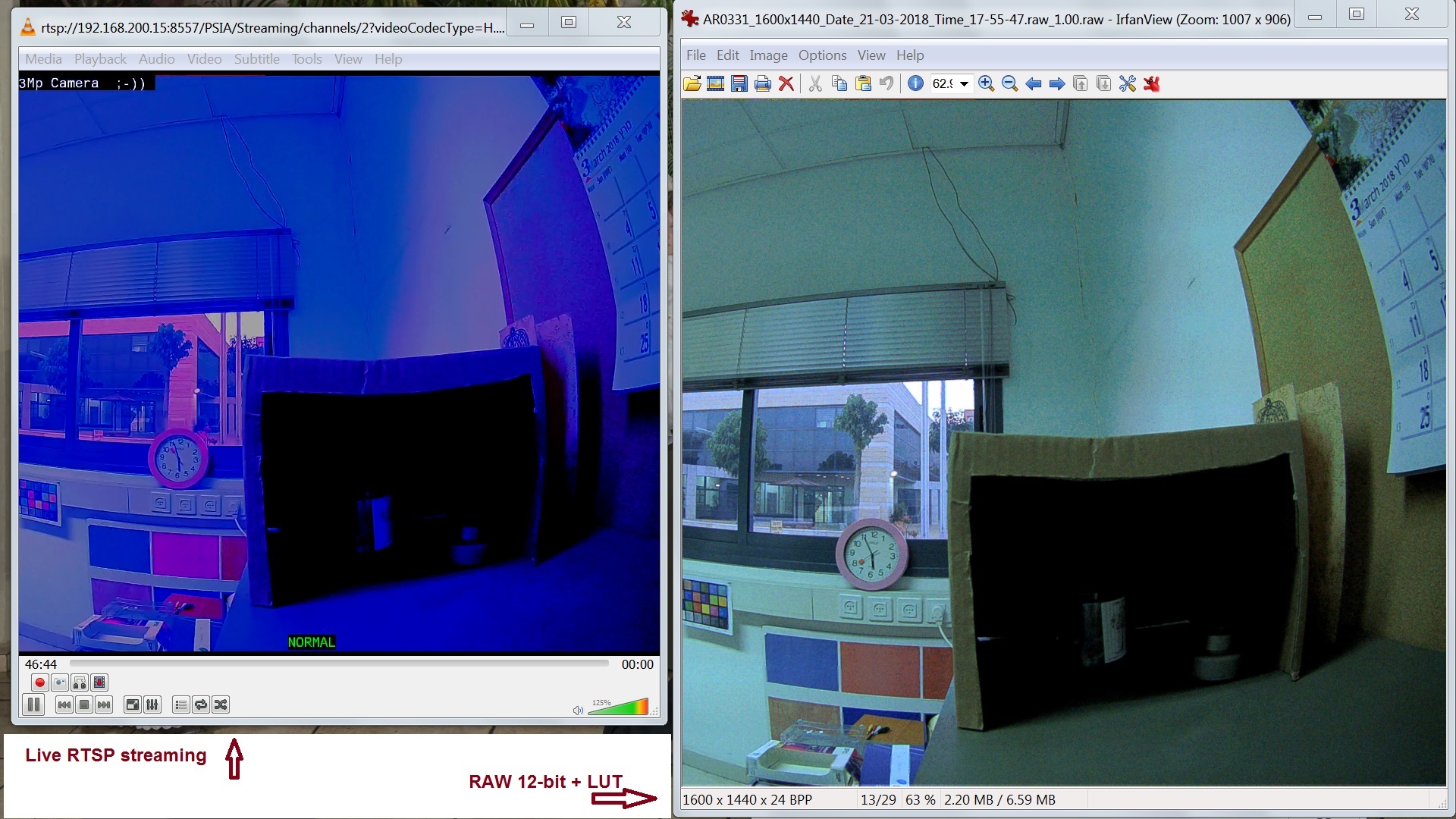
  • The RAW 12-bit picture (compressed with gamma = 1.0) to 8-bit shows perfect color. This frame is exactly what is output from the sensor before the CameraLink.

    The H264 picture received at the end of all the IPNC links is shown as the RTSP streaming.

    Why are the colors so changed? I can see all of the DCC register settings in the DCC tuning program - but I haven't figured out how to download them to a file in order to post here.

    ALTM pedestal is set to 0xA8 (168) and i left the DCC settings as default. 

    BTW, is there a special set of DCC settings for the AR0331 in HDR mode? (a *.bin file that should be upladed to the camera)

    At this point we can assume that the RAW picture is captured correctly - and with a simple LUT table (using gamma 1.0) is displayed OK.

    Now the question is what is happening in the IPNC_RDK to corrupt the colors, etc.

    Thanks for any ideas.

  • Hi Mechi,

    The pedestal in your raw after ALTM looks like 0.
    Could you please share the captured raw and yuv data files with the color checker in the view?

    Another thing to try is to update black level in ISIF to 0 from DCC tuning tool at run time (set sensor pedestal to 0 first) and check the result.
    After setting the black level to 0 in the tuning tool plugin and exporting to xml/bin, press the button of "updates the current plugin DCC file (immediate, non-persistent)".

  • Thanks Gang.

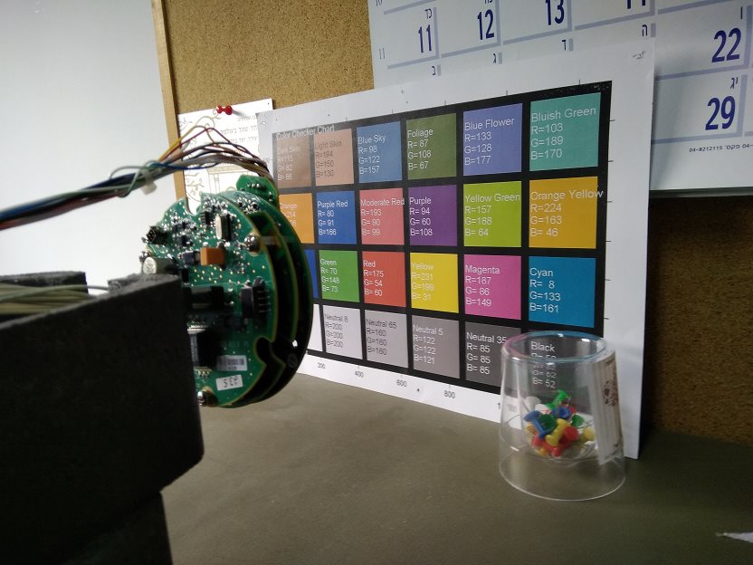
    I'll attach a picture from my cellphone, a YUV and a RAW 12-bit. Resolution is 1600x1440. 

    I compressed the files. Attached please find the ISIF register definitions (in jpg from screen shot) AR0331_1600x1440_Date_22-03-2018_Time_17-23-38.zipdcc_default.bin.zip and the AR0331 default_dcc.bin (with suffix zip - though not compressed) file used at the moment.

    .

  • The pedestal in the raw file is 0 (not 168) and therefore the black level in ISIF shall be set to 0.

    However, the color in the attached YUV file looks worse than I would expect even with the wrong -168 black level.
    The attached raw file is badly overexposed, but attached yuv image is much darker.
    Something is wrong.

    Your screen shot of the raw above with a bigger view has good exposure.
    Can you send me that raw file as well?
  • Attached is a zip file of the RAW 12-bit (expanded to 16-bit) data and the YUV.

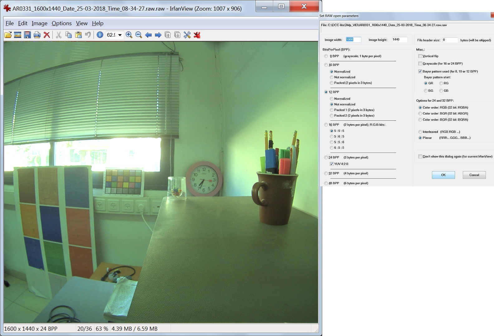
    Attached is a screenshot of the same RAW file viewed in IrfanView - colors are definitely true to life.

    I tried changing the ISIF_CLDCLOFST to 0 but the picture worsened and was much more purplish. 3Mp_VID.zip

  • The RAW frames come as 12-bit compressed - which is what I sent you on Thursday.
    Today I ran a small program to expand the 12-bit to 16-bit in which 4 MSB are always 0, and can be viewed.
  • Mechi,

    This raw image has a much higher black level, but it is probably due to the strong lens flare instead of the sensor pedestal.

    From these images, I think AWB and color correction have to be tuned for you camera module.
    To do that, it is better to tune everything in the linear sensor mode first to get the best image quality and then check the image quality in WDR sensor mode and make some adjustment as necessary.

    The second issue is that the gamma curve in IPIPE seems to be turned off (or linear) when I look at the captured YUV images.
    It reduces the dynamic range significantly.
    When tuning color in linear sensor mode, the gamma curve has to be set properly (e.g., the default one in RDK or BT709 gamma).

    After tuning everything properly in linear sensor mode and getting good image quality, you may change sensor to WDR mode with ALTM on and see what adjustment shall be needed.

    Tuning could be quite difficult if you don't have any experience and the necessary equipment. In that case, it is better to have a 3rd party do it for you.

    Gang

  • Hello Gang,

    I think one important premise is not being understood!!

    We are receiving a very high quality HDR image from the AR0331 sensor.

    We are NOT using the WDR link in the IPNC. We do NOT want to use any imaging pipeline or AWB from the IPNC.

    All I want is that the IPNC should get the 12-bit picture and transform it into 8-bit with the same simple LUT of gamma=1 expansion that the IrfanView program uses.

    Please - answer the first questions in this conversation - where is the 12-bit converted to 8-bit and how can I turn off all interference, so that the HDR AR0331 frame remains as it leaves the sensor?

    Thanks,
    Mechi
  • See even the title of the whole conversation...
    Thanks
  • Hi Mechi,

    You misunderstand the processing required in this situation.
    I have explained it previously and let me try to do it again.

    1. In linear sensor mode, the sensor outputs 12-bit linear Bayer pattern, and then this 12-bit linear Bayer pattern is converted to 8-bit YUV by the DM8127 H/W ISP pipeline and AE/AWB S/W running on TDA3-ARM.
    2. In WDR sensor mode with WDR link on, the sensor outputs 12-bit WDR Bayer pattern (PWL companded from 16-bit linear Bayer pattern), and WDR link S/W running on DM8127-EVE tone maps the 12-bit WDR Bayer pattern to 12-bit tone mapped Bayer pattern (dynamic range is compressed to 12-bit from 16-bit), and then DM8127 H/W ISP pipeline and AE/AWB S/W convert the 12-bit tone mapped Bayer pattern to 8-bit YUV.
    3. In WDR sensor mode with sensor ALTM mode on, the sensor outputs 12-bit tone mapped Bayer pattern (dynamic range is compressed from 12-bit from 16-bit), and then DM8127 H/W ISP pipeline and AE/AWB S/W convert the 12-bit tone mapped Bayer pattern to 8-bit YUV.

    There are 2 steps in processing above.
    1. WDR tone mapping: from 12-bit PWL WDR Bayer pattern or 16-bit linear WDR Bayer pattern to 12-bit tone mapped Bayer pattern.
    This can be done with either WDR link on DM8127-EVE or sensor ALTM.
    2. Raw conversion: from 12-bit Bayer pattern (either linear in linear sensor mode, or tone mapped in WDR sensor mode) to 8-bit YUV
    This can be done only by DM8127 H/W ISP and AE/AWB S/W on DM8127-ARM.
    AE also controls the sensor exposure and analog gain in addition to ISP digital gain, which is crucial for the camera system.

    In your situation with ALTM on, ISP pipeline H/W and AE/AWB are both required to convert 12-bit tone mapped Bayer pattern to 8-bit YUV.
    Bayer pattern is in 1 color per pixel raw format and ISP H/W is required to do noise filtering, bad pixel removal, color interpolation (demosaicing), color correction, gamma correction, and RGB to YUV conversion, edge sharpening, etc.
    You cannot simply take 8 bits from 12-bit Bayer pattern to get an output image with good image quality.
    I suppose Irfanview simply takes 8MSBs and do very simple demosaicing which give very low image quality (I cannot install Irfanview because it is not allowed at TI).
    Of course, for DM8127 ISP, tuning is required to achieve good image quality (with bad tuning parameters, image quality can get worse).

    I have some old 2012 DM365 IPNC AR0331 raw/yuv lab test images (linear sensor mode) to attached here later.
    You may open the raw images in Irfanview and compare to the yuv images from DM36x IPNC H/W ISP.
    I hope you may see the difference in color (both WB tint and color correction) and image details.

    Without proper AWB calibration, the overall color tone will be wrong.
    In your screen capture of the YUV image, there is strong purple color cast which is caused by improper calibration of AWB (AWB in RDK is calibration for TI IPNC reference design camera and lens module, and therefore it does not work with your camera module).
    In your Irfanview screen capture, there is a strong green color cast which is due to the lack of WB. (Iranview does a simple raw conversion with demosaicing and probably dropping 4LSBs, but does not do WB).

    BTW, the ALTM Bayer pattern you attached previously has limited quality in term of WDR tone mapping, exposure, and contrast.
    For the one with the window, the scene outside the window is completely saturated while the inside is heavily overexposed with poor overall contrast.
    For the earlier one with only the chart, the expose and contrast issue is similar.
    The cause of overexposure and poor contrast may be from auto exposure and/or ALTM.
    I am not familiar with this sensor ALTM, but I am sure tuning sensor ALTM and sensor exposure control for WDR use case is not trivial.

    I hope my explanations above are helpful for you to understand the situation.
    The recommended process of image quality tuning is to start with linear sensor mode to achieve image quality similar to the DM365 IPNC lab test images first.
    Then move to WDR mode to tune ALTM and WDR exposure control as part of AE control, and make other necessary (and expected to be small) ISP tuning changes.
    For your particular project, it is better to go with a 3rd party who has the experience and equipment.

    Back to your questions, AWB is definitely required for a camera.
    Unless the sensor has builtin AWB, you will have to run AWB on DM8127 (AE is similar).
    If you want to disable AWB, you may do it in RDK S/W, but I am not familiar with S/W and cannot tell you how to.
    I heard it was possible to disable AWB in DCC tuning tool manually at run time in "algorithm view" (just for run time experiment, no persistent).
    I have not done it myself, you may see if it is available in your version.
    If you want to change the gamma table, follow the IPIPE gamma correction section in the NDA document you have and then try to change it to what you like in DCC tuning tool.
  • >> You cannot simply take 8 bits from 12-bit Bayer pattern to get an output image with good image quality.

    We don't...

    >>  BTW, the ALTM Bayer pattern you attached previously has limited quality in term of WDR tone mapping, exposure, and contrast.

    I know - and am fully aware of this. I will be working on this with an expert who knows this sensor and will be able to output high quality WDR pictures.

    This was written by a colleague (some points may be repeated):

    The DCC delivers raw 12-bit Bayer from the sensor – regardless of the sensor delivering HDR-companded or ALTM 12-bit images.

    The image data returned from the DCC has each row of Bayer pixels 12-bit packed – leaving unused bytes with 0x80 value at the last quarter of the row.

    The images – after expanding each row to full 16-bit pixel values and applying a trivial Gamma-1 decompanding are great images – as is – without further color processing.

    The expected image depth is provided nicely without using IPNC-WDR link.

    The default current IPNC processing chain takes these great images and generates purplish images.

    As a first step, we want to configure the IPNC such that in the default non-WDR mode - with AE and AWB off - the IPNC streams images of comparable quality to those extracted by the DCC.

    In other words, we want the same link configuration used in the 10MP project to accept the AR0331 images.

    How do we accomplish this?

    I'm thinking that maybe I'll try the DCC_MT9J003.bin file provided...I wonder if that would help.

    Thanks,

    Mechi

  • I tried using the DCC file provided for the 10Mp sensor - but with the same purplish output...

  • >> The image data returned from the DCC has each row of Bayer pixels 12-bit packed – leaving unused bytes with 0x80 value at the last quarter of the row.

    This captured image is packed lossless from sensor output.

    >> The images – after expanding each row to full 16-bit pixel values and applying a trivial Gamma-1 decompanding are great images – as is – without further color processing.

    I have looked at all raw images you attached or showed as screen snapshots earlier and they all have poor quality.
    To get good ones in DCC tuning tool, you need to control sensor exposure properly from DM8127.
    Since RDK does support this ALTM sensor mode as Anand mentioned, AE cannot work properly with ALTM mode and therefore you won't be able to get well exposed raw images in general unless you are lucky at some scenes.

    To get your camera working fine with ALTM at the end, you probably need to rewrite AE.

    >> The expected image depth is provided nicely without using IPNC-WDR link.

    Yes, this is expected.
    The WDR link has the same function has ALTM in sensor, it shall be disabled when ALTM is on.

    >> The default current IPNC processing chain takes these great images and generates purplish images.

    That is because the current IPNC tuning is done for the TI IPNC reference design cameras which is different from your camera lens module. You have to do tuning on your camera to get good quality.

    >> As a first step, we want to configure the IPNC such that in the default non-WDR mode - with AE and AWB off - the IPNC streams images of comparable quality to those extracted by the DCC.

    You may change ISP parameters in DCC tuning tool as you can capture raw/yuv images from the tuning tool.
    If not, you have to change it in S/W.
    AE/AWB may be disabled in DCC tuning tool as well, but I am not 100% sure.
    You may go through the DCC tuning tool documents or have a 3rd party to help you (I won't not able to help you here).

    >> In other words, we want the same link configuration used in the 10MP project to accept the AR0331 images.

    >> How do we accomplish this?

    I am not aware of this 10MP project.

  • Thanks Gang.

    That was a very detailed and information-filled answer.

    We have successfully received very good 12-bit RAW HDR frames.

    Something in the DCC/IPNC chain is removing parts of the details and changing the contrast and brightness of the frames.

    Here are some more specific questions:

    1) In IssAlg_capt2AProcessTI (/ti_tools/iss_03_80_00_00/packages/ti/psp/iss/drivers/alg/2A/src/issdrv_alg2AApi.c) a gamma LUT table can be used (gamma_iss_default_table) to convert 10-bit to 8-bit (1024 --> 256 values). My data is coming from the AR0331 sensor as 12-bit. Should I supply a gamma table from 12 bit --> 8 bit or from 10 bit --> 8 bit.

    In which module of the pipeline is the frame compressed from 12-bits to 10 bits?

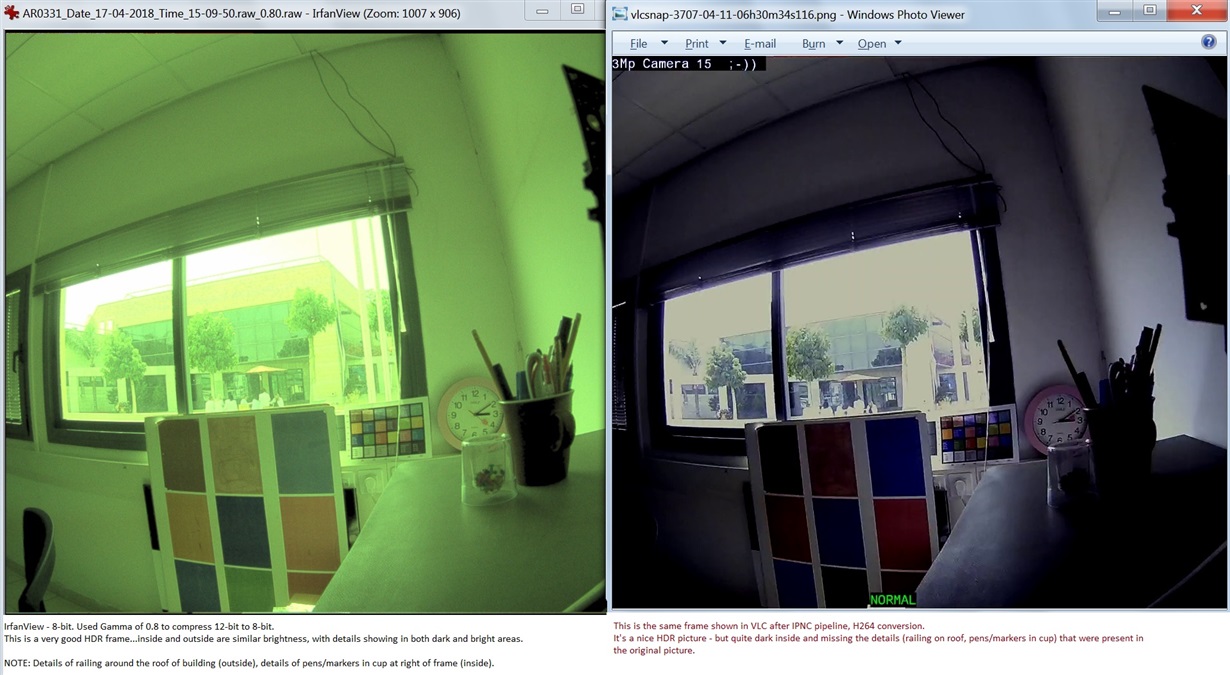
    2) We see that the AR0331 sensor software is able, with a CCM and AWB, to create a fine, detailed and uniformly bright picture. In the attached JPG, the RAW 12-bit image has much detail with uniform brightness. After the IPNC pipeline and conversion to H264, the final picture is missing much detail. How can all the detail be preserved and the CCM applied?

    Thanks,

    Mechi HDR_frames_8bit_12bit.zip

  • Hi Mechi,

    It sounds like you made good progress.

    >> 1) In IssAlg_capt2AProcessTI (/ti_tools/iss_03_80_00_00/packages/ti/psp/iss/drivers/alg/2A/src/issdrv_alg2AApi.c) a gamma LUT table can be used (gamma_iss_default_table) to convert 10-bit to 8-bit (1024 --> 256 values). My data is coming from the AR0331 sensor as 12-bit. Should I supply a gamma table from 12 bit --> 8 bit or from 10 bit --> 8 bit.

    I am not sure about s/w implementation. The H/W ISP block IPIPE-Gamma has a 512-entry LUT of 10-bit each. The s/w may use a different LUT on different platforms. Sometimes, it could be a 1024-entry LUT with 8-bit each in s/w and conversion to H/W format is done by s/w. You may check the current LUT format (512 or 1024 entries) and follow the same.

    If you have ALTM in sensor, then you could start with the gamma curve of BT709 with proper format or follow ALTM's recommendation for gamma.

    >> In which module of the pipeline is the frame compressed from 12-bits to 10 bits?

    IPIPE-Gamma

    >> 2) We see that the AR0331 sensor software is able, with a CCM and AWB, to create a fine, detailed and uniformly bright picture. In the attached JPG, the RAW 12-bit image has much detail with uniform brightness. After the IPNC pipeline and conversion to H264, the final picture is missing much detail. How can all the detail be preserved and the CCM applied?

    The streaming video is very dark while "HDR_frame_12bit_1600x1440.raw" is very bright (I suppose this is the raw from sensor with ALTM). There must be some small gain and linear gamma curve to make it so dark, e.g., you use the top 8-bit of the 12-bit from raw may have similar effects.

    The image quality of "HDR_frame_12bit_1600x1440.raw" still have some issues. If you look at the front of the cup, there are many pixels clipped to very small values (2) from around 100~200 in neighborhood.

  • Hello Gang,
    From what I understand, using the DCC tool to configure the IPIPE, ISIF, IPIPEIF and gamma curves would be the way to configure 12-bit RAW frames to 8-bit YUV.
    I shouldn't need any programmatic changes in the actual code.
    Is this correct?
    Thanks,
    Mechi
  • Hi Mechi,

    Most ISP parameters are supported by DCC.
    You may change those parameters in DCC tuning tool and press a button to see the effect on H/W.
    If you see it is effective, then there shall be no code changes required (probably only a new DCC bin file).
    Best,
    Gang