This thread has been locked.

If you have a related question, please click the "Ask a related question" button in the top right corner. The newly created question will be automatically linked to this question.

TMS320DM8168: GP1[9]/GPMC_A[27] Internal Pull Down Enable

Part Number: TMS320DM8168

Hi,

Table 4.5 GPIO Terminal Functions of 8168 datasheet states that the state for GPMC_A[27]/GP1[9] as below:

PULL: DIS / IPD
DRIVE: Z / Z
DVDD_3P3

PULL: A / B, where:

A is the state of the internal pull resistor during POR reset
B is the state of the internal pull resistor after POR and Warm reset are de-asserted and during Warm reset
IPD = Internal Pulldown Enabled, IPU = Internal Pullup Enabled, DIS = Internal Pull Disabled
DRIVE: A / B, where;
A is the driving state of the pin during POR reset
B is the driving state of the pin after POR and Warm reset are de-asserted and during Warm reset
H = Driving High, L = Driving Low, Z = 3-State

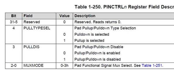
Also the technical reference manual () shows that the register values for PINCTRL189 are set to

PULLTYPESEL = 0 (Pulldown selected)

PULLDIS = 0 (Pullup or Pulldown enabled)

Is there a way to hold the internal pull down resistor during the POR?

Thanks.

  • Hi Amol,

    No, I do not think you can enable the internal pull down resistor of pin K8 during POR. You should use external pull down resistor to hold the line during POR.

    Regards,
    Pavel
  • Thanks Pavel,

    Can we disable the pulldown for GP1[9] from uboot using the below PINCTRLn register:

    I tried changing this bit from uboot but it didn't take any effect.

    Thanks

  • Hi Amol,

    Yes, that should be possible.

    Can you provide me u-boot console log of your steps?

    Regards,
    Pavel
  • Hi Pavel,

    I got the required settings today. I am able to pulup/pulldown on GPIO1[9] and even disable it. However we observed that the GPIO1[9]  is not going low enough.  It is going to 1.2875V only.  There is no other load on this pin except one device with an internal pull-up of about 22K ohms.

    The code changes for enabling gpio1 has been added to board/ti/ti8168/evm.c in peripheral_enable() function just after gpio0 is enabled. The code is as below


    #ifdef CONFIG_ENABLE_GPIO1
        __raw_writel(0x2, CM_ALWON_GPIO_1_CLKCTRL);
        while((__raw_readl(CM_ALWON_GPIO_1_CLKCTRL) & 0x3) != 0x2);


        __raw_writel(0x2, 0x48140AF0);        /* Pull Down on GPIO1[9] */

        // __raw_writel(0x12, 0x48140AF0);        /* Pull Up on GPIO1[9] */

        gpio1_oe = __raw_readl(0x4804C134);
        gpio1_oe = gpio1_oe & 0xFFFFFDFF;
        __raw_writel(gpio1_oe , 0x4804C134);

        gpio1_9_data = 0x00000200;
        __raw_writel(gpio1_9_data, 0x4804C190);      /* Use ClearDataOut */
        //delay(1000);
        gpio1_9_data = 0x00000200;
        __raw_writel(gpio1_9_data, 0x4804C194);    /* Use SetDataOut */
    #endif

    Any reason what could be wrong? The CONFIG_ENABLE_GPIO1 is enabled for uboot and disabled for MLO.

    Thanks,

  • Amol,

    Amol N said:
    However we observed that the GPIO1[9]  is not going low enough.  It is going to 1.2875V only.  There is no other load on this pin except one device with an internal pull-up of about 22K ohms.

    The internal pull down/up resistor is very weak, and thus impacted by the external device pull up. I would suggest you to use external pull down resistor, as the internal one is not enough for your design.

    Regards,
    Pavel