This thread has been locked.

If you have a related question, please click the "Ask a related question" button in the top right corner. The newly created question will be automatically linked to this question.

AM1808 uPP peripheral send wrong data after channel reconfiguration

Other Parts Discussed in Thread: AM1808, OMAP-L138

In our design we use AM1808 and FPGA. FPGA is configured and data are transferred through uPP peripheral. We use Linux as operating system, and uPP driver based on TI's provided BIOS/CSL driver.

uPP operate in two modes:

1. Data mode, where data from FPGA are transferred by Channel A (Channel A is configured as INPUT) and data to FPGA are transferred by Channel B (B is OUTPUT).

2. Configuration mode, for FPGA content load, where Channel A is OUTPUT, and Channel B is configured as INPUT.


Sometimes we need to change FPGA content. Then we change uPP interface configuration, load new FPGA content, and change interface back. It works fine until we do not read from FPGA (in Data mode) before uPP reconfiguration. If we do read before reconfiguration, then FPGA content load fail, because uPP do not send correct data to Channel A. It seems like first 64 bytes of programmed DMA transfer disappear (uPP START signal is generated properly, but in wrong place?). We have captured uPP registers logs in time of DMA transfer programming, and registers content is same for both case (OK and Fail). In time of reconfiguration uPP peripheral software reset is performed (we test also reset uPP multiple times). Could someone, please, suggest what's wrong? 

Regards,

Slavomir

Some details:

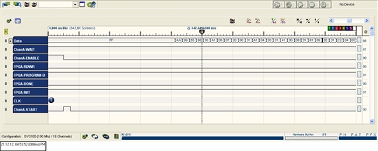
Here is a picture with correct data sent. Couple of 0xFF at beginnig followed 0xAA 0x99... uPP channel A is configured as output. Channel B configured as input (tested also as uncofigured - no matter).

From logs - printed part of buffer content - address 0xc5d00000:
0xff 0xff 0xff 0xff 0xff 0xff 0xff 0xff 0xff 0xff 0xff 0xff 0xff 0xff 0xff 0xff
0xaa 0x99 0x55 0x66 0x30 0xa1 0x00 0x07 0x20 0x00 0x31 0xa1 0x04 0x30 0x31 0x41
0x3d 0x08 0x31 0x61 0x09 0xee 0x31 0xc2 0x04 0x00 0x20 0x93 0x30 0xe1 0x00 0xcf
0x30 0xc1 0x00 0x81 0x20 0x00 0x20 0x00 0x20 0x00 0x20 0x00 0x20 0x00 0x20 0x00

and values writed to uPP registers:
window: 0xc5d00000
line|bytes: 0x000e7ff8
offset: 0x00007ff8

Then we reconfigure uPP interface to ChA as input, ChB as output, send and read some data to/from FPGA. Read is impotrant. Without read everything work OK.

In time, when FPGA content need to be changed uPP interface is reconfigured to "configuration mode ", and data are sent (for this case data are same).

Part of interface reconfiguration is also sw reset of uPP peripheral.

Printed buffer content is same - buffer address 0xc5d00000:
0xff 0xff 0xff 0xff 0xff 0xff 0xff 0xff 0xff 0xff 0xff 0xff 0xff 0xff 0xff 0xff
0xaa 0x99 0x55 0x66 0x30 0xa1 0x00 0x07 0x20 0x00 0x31 0xa1 0x04 0x30 0x31 0x41
0x3d 0x08 0x31 0x61 0x09 0xee 0x31 0xc2 0x04 0x00 0x20 0x93 0x30 0xe1 0x00 0xcf
0x30 0xc1 0x00 0x81 0x20 0x00 0x20 0x00 0x20 0x00 0x20 0x00 0x20 0x00 0x20 0x00

and data to DMA registers are also same
window: 0xc5d00000
line|bytes: 0x000e7ff8
offset: 0x00007ff8

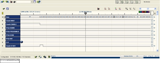
But uPP send wrong data. First 64 bytes are missing.

  • UPDATE: we found, that, if DLB is activated, this error never happend. Why? When DLB is not activated, in time of FPGA configuration, FPGA is in reset state and CLK for read channel is inactive. Could be problem there?

    Slavomir.

  • No one know? No idea? Support team?

    Regards,

    Slavomir.

  • Hi Slavomir,

    I've had some experiences working with the uPP peripheral, though it was on the L138 Module. Perhaps some of what I've learned could be helpful to your situation.

    It's important to note that I've only interfaced to the peripheral via a driver I wrote for the DSP core on the L138. When first working with the peripheral I did attempt to use some drivers provided by TI (I believe they were BIOS/CSL drivers, but it was years ago, so I might not be remembering the name correctly). We ultimately decided to write our own driver because while the ones from TI did seem to work correctly, they produced odd delays in data transmission and did not allow for the throughput we needed.

    So, while our situations are not the same, perhaps some of the oddities I've had to work around with the uPP might explain or help with the issues you are having.

    First, I'm not sure how this works through the BIOS/CSL driver, but are you getting any error reports from the uPP peripheral? There is a register called the uPP Interrupt Enabled Status Register (UPIER) that reports certain error conditions. If any of these errors are triggering that might give you a better idea as to what is going on when you see this lost data.

    Second, what clock source are you using when a channel is set in output mode? In the L138 you can select one of three output clocks for an output channel. We've experienced random lock ups and false error reporting when using UPP_2xTXCLK and PLL1_SYSCLK2. PLL0_SYSCLK2 is the only clock we've not had uPP transmit problems with.

    Third, what procedure are you following for the uPP peripheral software reset? The TRM spells out specific steps for a proper software reset. The driver I wrote was initially was doing this incorrectly and would lead to odd behavior after resetting the peripheral.

    Hope this is of some help.

    \Greg

  • Hi Greg,

    thanks for response. We use BIOS/CSL with a little modification, and throughput is fine for our application without any lags.

    As clock source is PLL1_SYSCLK2 used. I found article "uPP Design Considerations" where false events are described, and some false events really occur (data seems to be transfered fine). We prepare switch to PLL0_SYSCLK2.

    Regard uPP software reset, function from TI driver is used. I suppose it's writen correctly. At least for first look it seems to be fine, are there some waits for 200 cycles, and so on, like in TRM.

    Anyway, due to no response from TI, we found workaround for our application, and for now we do not need to change channel configuration. Hope, TI will release new version of documentation, where all known errors will be mentioned. In current documentation is many word, but few information.

    Thanks,

    Slavomir

  • Hi Greg,

    I very excited to see your reply in this question. I am developing upp driver on am1808( mity1808F, change core clk to 450MHz ), and meet the same problem that your meet before and stated in "uPP Transmission Problems (UOR Error on DMA Channel I)".

    the system continued to print error inf ---- "UORI", I refered to the reference guide and found it's the DMA problem. Then I searched on the internet and see your word in the  "uPP Transmission Problems (UOR Error on DMA Channel I)", which you wrote in the year 2011. I switch the clock from PLL1 SYSCLK2 to PLL0 SYSCLK2. Then, debug uart was influenced and I use ssh from ethernet instead, however, the UORI remains. This error may randomly disappear when I rerun my unchanged program.

    So, if the 2Xtxclk is necessary for UPP transmission? or did you find other ways to solve this problem.

    best wishes & looking forward to your reply

    Alex

  • Hi Alex,


    Changing the transmit clock to PLL0_SYSCLK2 on the OMAP-L138 always solved the issue for me. One thing you may want to consider is that your core clock is running at 450 MHz. In the L138, unless you took special measures, PLL0_SYSCLK2 was 1/4 the speed of the core clock. So in your case your transmit clock might actually be 112.5 MHz. This is out of spec for the uPP. I'm not too familiar with the AM1808, so I'm not sure if the same rules apply, but I would check that when selecting PLL0_SYSCLK2 your transmit clock is still 75 MHz.

    Hope this is helpful.

    \Greg

  • Hi,

    I am working on UPP driver in linux for AM1808 board. I have configured the CH-A (TX) and CH-B (RX),  dual channel mode in loopback. I am always getting data as ZERO. Could you please help on the issue.

    What should be the 2xTX_CLOCK Configuration for upp?

    Thanks

    Mrudula

  • Hi Mrudula,


    Selecting PLL0_SYSCLK2 for 2xTX_CLOCK always worked best for us. I have not worked with the uPP peripheral in loop back mode, so I don't have much to offer as to why that is not working for you.

    Thanks,

    \Greg

  • Hi All,

    Have a great day. 

    Subject: Transfer parallel data from AM1808 to customer board with WAIT activated.

    Board Setup: AM1808 board  interfaced with customer board (receiver chip).

    The setup is AM1808 will send 8 bit parallel data on channel-B (transmit mode) along with CLOCK (output) and ENABLE (output) which act as DATA-VALID.  The receiver chip will capture data when ENABLE=1.  This setup works fine as expected. i.e. The data transfer from AM1808 to receiver chip is successful.

    Now the receiver chip want's to halt the transfer (if its internal FIFO goes to almost full) so we have configured WAIT (input to AM1808) signal with ACTIVE high polarity.  Here are the more register setting for uPP interface.

    UPICR.TRISB=0 

    UPICR.WAITB=1 (WAIT is enabled for channel-B)

    UPICR.WAITPOLB=0 (WAIT is configured as active HIGH)

    UPCTL.MODE[1:0] [Field 1to 0] = 1h (All transmit mode)

    The issue we noticed is AM1808 is continue sending DATA even though WAIT is set to logical HIGH.  The expected behavior is AM1808 should stop sending data. Also observed that WAIT signal is forcefully driven to active LOW by AM1808 even though we configured WAIT as INPUT.  

    Please help us to solve above issue, I am ready to share more details if required. Thanks a lot.

    Best Regards,

    Magesh S


  • Hi Magesh,

    Could you please create new post for your issue because the post seems to be old and it could get less intervene by others who they are willing to help on this our TI E2E community.

  • Sure, I have already created a post and got reply. Please refer to http://e2e.ti.com/support/dsp/omap_applications_processors/f/42/p/238280/1276358.aspx#1276358

    Best Regards,

    Magesh S

  • Opps, here is the updated LINK.

    http://e2e.ti.com/support/dsp/omap_applications_processors/f/42/t/363290.aspx

    best Regards,

    Magesh S

  • Hi Magesh,

    Thank you, surely we will address this issue.