This thread has been locked.

If you have a related question, please click the "Ask a related question" button in the top right corner. The newly created question will be automatically linked to this question.

SPI slave is missing spi clocks?

Other Parts Discussed in Thread: OMAP-L138, OMAPL138

Hello all,

I am using OMAP-L138 and it is a SPI slave with EDMA3 to exchange packets with an external SPI master.

It works fine but it sometimes fails to exchange packets.

My problem is that EDMA3 sometimes does not complete leaving last single byte trasnfer not completed.

It seems that SPI in L138 is missing 1 or 2 SPI clocks in transfer and that it does not reach to completion of EDMA.

In fact, after sending an extra 1 or 2 SPI clocks from the external SPI master, which is a Stellaris, by manipulating GPIO registers directly to transtion rising/falling SPI clocks, then EDMA3 in the OMAP-L138 completes. And in addition the received data in OMAP are like this:

received data : 00 01 02 03 04 05 06 07 08 09 0A 0B 0C 0D 0E 0F 10 11 12 13 14 15 16 17 18 19 1A 1B 1C 1D 1E 1F 20 21 22 23 24 25 26 27 28 A4 A8 AC B0 B4 B8 BC C0 C4 C8 CC D0 D4 D8 DC E0 E4 E8

expected data: 00 01 02 03 04 05 06 07 08 09 0A 0B 0C 0D 0E 0F 10 11 12 13 14 15 16 17 18 19 1A 1B 1C 1D 1E 1F 20 21 22 23 24 25 26 27 28 29 2A 2B 2C 2D 2E 2F 30 31 32 33 34 35 36 37 38 39 3A 3B

Waveform in osciloscope looks fine. I do not think that this problem is from hardware/waveform issue.

Does anyone give me a suggestion?

Transfer rate is currently from 6 ~ 10MHz.

At 6.66MHz, it nevers fails.

At 8.00MHz, it sometimes fails.

At 10.00MHz, it frequently fails.

I am planing to boost it up to 20MHz of SPI transfer rate. Is this possible?

Thanks,

  • Hi Morizzo,

    Thanks for your post.

    Usually, the SPI master can monitor the slave SPIx_ENA activity to detect any condition to happen a desynchronization event. Some possible conditions are:

    1. Master or slave device would have been reset during a transmission.

    2. Software reset of the SPI module during Tx. would have been asserted.

    3. Incorrect SPI pin configuration which would cause the SPIx_ENA pin to behave incorrectly.

    Signal integrity problem will cause additional clocks to be recognized by the slave.

    With respect to above possilble conditons, the master can detect two desynchronization error conditions on the SPIx_ENA pin:

    1. Slave deasserts SPIx_ENA after a transmission has begun, but before it completes.

    2. Slave fails to deassert SPIx_ENA within a certain time period after the completion of the last bit of the transmission.

    To spot out second error condition, the SPI module which includes an eight-bit counter with a timeout value that can be configured through the T2EDELAY field in the SPI delay register (SPIDELAY).

    If any of the above desynchronization events needs to be detected, you should possibly enable the DESYNC bit in the SPI receive buffer register (SPIBUF) and the DESYNCFLG bit in the SPI flag register (SPIFLG) which needs to be set to assert a desynchronization error interrupt.

    I would recommend you to set the above register bits to assert any desynchronization error interrupts for your incomplete EDMA transfer case. Also configure the T2EDELAY field in the SPI delay register to check for error condition 2.

    For more details, please refer section 30.2.14.3 in the omapl138 TRM as below:

    http://www.ti.com/lit/ug/spruh77a/spruh77a.pdf

    Kindly try out all the possible usecases to spot out the desynchronization error conditions, if any.

    Thanks & regards,

    Sivaraj K

    -------------------------------------------------------------------------------------------------------
    Please click the Verify Answer button on this post if it answers your question.
    ------------------------------------------------------------------------------------------------------

  • Hi Sivaraj,

    Thank you for your quick reply and listing up the conditions I should look into.

    I forgot to write an important point in the previous post.

    I am using 3-pin spi slave mode. So I suppose that condition on SPIx_ENA / SPIx_SCSn pins does not matter. Is this correct?

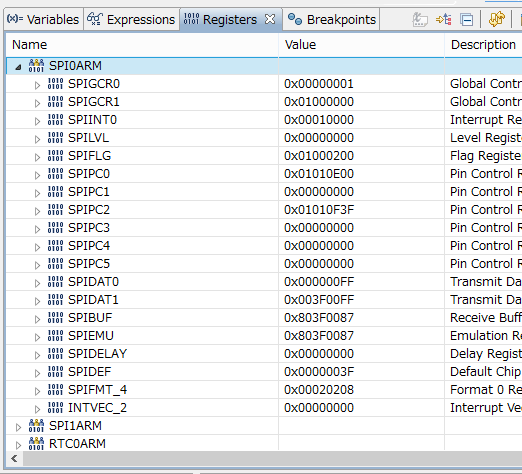
    Here is a pic of SPI registers just after this problem occurs:

    It would be helpful if any comments on the register settings.

    I think that signal integrity is most possible cause in this case. But I have not seen any fault in signal swinging level, slew rate and rising/falling edge counts so far. I believe that the SPI master drives spi clock correctly in its signal quality and its count. Problem should be in SPI slave side.

    Anyway, I am going to check carefully each of what you pointed out and I will post again if I find something new.

    Thanks,

    Morzzo

  • Hi Sivaraj and all,


    I am still working on the issue in this post.

    I have a hypothetical idea about how the issue happens in OMAP-L138.

    Could anyone, hopefully TI engineer, please verify it from internal side of OMAP-L138?

    My hypothesis is:

    1.  EDMA transfer may not be in time. Remember that OMAP-L138 is SPI slave and SPI master keeps sending data even if receive data in SPI register is not cleared. The interval of EDMA request for SPI transfer is about 1usec @ 8Mbps with 8bit per word.

    2. Then, SPI peripheral will ignore incoming clock/data by bit, not by word, when received data is still in the rx register due to delayed EDMA transfer.

    3. When EDMA transfer finishes and clears rx register, then SPI peripheral starts receiving incoming data/clocks again despite word boundary.

    4. In result, following data is out of word boundary.

    If this is true, I think that OMAP-L138 is not suitable for receiving SPI stream as SPI slave.

    And how can I boost up response of EDMA request? I have already tried to change MSTPRIx registers to put EDMA3_0_TC0 higher priority but it does not improve very much.

    Can I get a internal timing chart of EDMA controller in OMAP-L138?

    Thanks in advance,

    Morizzo

  • Hi,

    I think, in order to boost the EDMA responses to their request, you could try setting the DMAREQEN after setting up the EDMA transfer and not before.

    Regarding SPI slave problems, I have few questions below:

    1. How many clock pulses does the "SPITransmitData1" call generates on the "SPI1_CLK" Line? Could you please probe the SPI1_CLK line with a scope after you put the data on the SPIDAT1 register so, it must be with singe SPI transmit call?

    2. How many bytes does SPI send for each transaction which could be identified through probing the "SPI1_CLK" Line before and after the "SPITransmitData1" call?

    3. Also, check does any pullup happen in SPI0 since the SPI pins, by default, all have Internal Pullup (IPU) resistors and perhaps the slave is not strong enough to pull down the line. May be, you could review the below E2E post for probable OMAPL138 SPI1 problems in detail and validate the suggestion provided by Norman on the same post:

    https://e2e.ti.com/support/dsp/omap_applications_processors/f/42/p/345403/1216469#pi317270=1

    Thanks & regards,

    Sivaraj K

    -------------------------------------------------------------------------------------------------------

    Please click the Verify Answer button on this post if it answers your question.

    ------------------------------------------------------------------------------------------------------

  • I am using TMS3206748 in SPI slave mode.

    I can run at 5MHz successfully. At 10MHz, randomly gio_submit() returns IOM_ENOPACKETS and also, sometimes callback function is not called.

    I checked out SPI slave specs and I should be able to run at 15MHz. 

    status = GIO_submit(spiHandle, IOM_READ,  &spi_dataparam, &len, &SpiCallbackFunction);

    oGPIO.GPIO_SetPinVal(DSP_IMX6_GPIO3, GPIO_PIN_LOW);//tell master to send clocks

    status = SEM_pend(&SEM_SPI0_Done, SYS_FOREVER); // callback function posts semaphore

    What I could be doing wrong or are there any limitations?

    Thanks & regards

    Manish

  • Are you using bare metal code or PSP?