This thread has been locked.

If you have a related question, please click the "Ask a related question" button in the top right corner. The newly created question will be automatically linked to this question.

Help on using the U-BOOT AND ARMUBL AND DSP UBL SPI1 FLASH

Hi

Team.

I am trying to change the default configuration of SPI0FLASH booting.That is mentioned in the Uboot source code and Arm-ubl and   DSP- ubl as we have our custom board That supports SPI1FLASH

As I am new to this I Need help on the initial start up!

I am trying to analyse the the code that is provided in the folder armubl and dspubl and try changing the register for SPI1 .

Let me know the Possible easier solution to configure it for SPI1  and what has to be modified w.r.t the SPI

Thank you

Deepak R

  • Hi Deepak,I presume that you are using OMAPL137 custom board.
    Try to find out the initialization code in DSP UBL and ARM UBL code then add support for SPI1.
    In u-boot, you could find the configuration file in include/configs/da830evm.h (if its OMAPL137 board)
    Please let me know if any issues.
  • tHANKS FOR RESPONSE!
    Working on it I will ask for any issues!
  • Hi,

    Thanks for your response on Cross Compiler !

    As next step I am trying to use the \Desktop\REL_LSP_02_20_00_05\PSP_02_20_00_05\board_utilities\dspubl 

    That has the ubl.c file that has the main() function I am trying to modify the code as my custom board of OMAPL137 supports SPI1 booting

    The following is the changes that is done 

    //DEVICE_LPSCTransition(0, 4, 0, PSC_ENABLE);--->ORIGINAL THAT HAS THE PSC0 MODULE ON
    
    DEVICE_LPSCTransition(1, 10, 0, PSC_ENABLE);---->MODIFIED PSC1 with SPI1 ,DOMAIN PSC_ENABLE 
     //DEVICE_pinmuxControl(7, 0xFFFFF000, 0x11111000);---->ORIGINAL THAT HAS THE VALUE TO ENABLE SPI0

    DEVICE_pinmuxControl(8, 0xF0000FFF, 0x10000111);----->//MODIFIED THAT HAS THE VALUE FOR SPI1-0,4,8,28 PINS ARE ACTIVATED DEVICE_pinmuxControl(9, 0x0000000F, 0x00000001);//ORIGINAL THAT HAS THE VALUE FOR SPI1-0 PINS ARE ACTIVATED DEVICE_pinmuxControl(13, 0xFF000000, 0x88000000);---->CONFIGURING THE GPIO PIN 0.0 AND 0.1 FOR LED TOGGLE

    Next change is that I have added a toggle function that toggles my led once the initialisation is done  the code is working fine for applications and its tested on other AIS

    typedef struct  {
        volatile unsigned int DIR;
        volatile unsigned int OUT_DATA;
        volatile unsigned int SET_DATA;
        volatile unsigned int CLR_DATA;
        volatile unsigned int IN_DATA;
        volatile unsigned int SET_RIS_TRIG;
        volatile unsigned int CLR_RIS_TRIG;
        volatile unsigned int SET_FAL_TRIG;
        volatile unsigned int CLR_FAL_TRIG;
        volatile unsigned int INTSTAT;
    } GpioBankRegs;
    
    #define GPIO_REGS_BASE                     	(0x01E26000u)
    #define GPIO_0_1 							(*(volatile GpioBankRegs*)(GPIO_REGS_BASE + 0x10u))
    #define GPIO_2_3                            (*(volatile GpioBankRegs*)(GPIO_REGS_BASE + 0x38u))
    #define GPIO_4_5                            (*(volatile GpioBankRegs*)(GPIO_REGS_BASE + 0x60u))
    #define GPIO_6_7                            (*(volatile GpioBankRegs*)(GPIO_REGS_BASE + 0x88u))
    #define GPIO_8                              (*(volatile GpioBankRegs*)(GPIO_REGS_BASE + 0xB0u))
    
    
    void led_tog()
    {
    	volatile unsigned int i = 0;
    	volatile unsigned int j = 0;
    	{
    	while(j < 10000)
    	GPIO_0_1.SET_DATA = 0x00000003;
    	for(i=0;i<100000;i++){}
    	GPIO_0_1.CLR_DATA = 0x00000003;
    	for(i=0;i<100000;i++){}
    	GPIO_0_1.SET_DATA = 0x00000003;
    	for(i=0;i<100000;i++){}
    	GPIO_0_1.CLR_DATA = 0x00000003;
    	//i++;
    	j++;
    	}

    I have also modified the SPI0 init to SPI1 inside the 

     hSPIMemInfo = SPI_MEM_open(1);///ORIGINALLY VALE WAS 0
    
      if (hSPIMemInfo == NULL)
        return E_FAIL;
     
      // Load ARM UBL into memory 
      SPI_MEM_readBytes(hSPIMemInfo, DEVICE_SPI_BOOT_ARM_UBL_OFFSET, DEVICE_SPI_BOOT_ARM_UBL_SIZE,
      				(Uint8*) DEVICE_ARM_UBL_LOAD_ADDR);
    
      // just return success
      return E_PASS;

    I am confident on the address macros of DEVICE_SPI_BOOT_ARM_UBL_OFFSET, DEVICE_SPI_BOOT_ARM_UBL_SIZE,

    DEVICE_ARM_UBL_LOAD_ADDR

    When I compile the code I get the spi-ubl.out file and have generated the AIS file correspondingly for SPI1 configuration

    When I try to add to dump the code to the board and reset 

    I dont find any toggling or booting of DSP

    My initial concern is that if that led toggles then I can proceed and change the ARM UBL

    NOT SURE WHAT IS GOING WRONG  !

    I have no knowledge on the linker.cmd file  which might be causing the issue!

    As I wanted to run this code on SDRAM-B, I have changed the address  as below 

     L2RAM : org = 0xc3000000, len = 0x1000000
    
    	//L2RAM		org=0x80000000 len=0x00010000 /* L2 RAM/Cache *-----ORIGINAL/
    	//L2RAM: org = 0xc3000000, len = 0x1000000
    }
    
    
    SECTIONS
    {
    	.text       > L2RAM
    	.const      > L2RAM
    	.bss        > L2RAM
    	.far		> L2RAM
    	.switch		> L2RAM
    	.stack      > L2RAM
    	.data       > L2RAM
    	.cinit		> L2RAM
    	.sysmem		> L2RAM
    	.cio		> L2RAM
    }

    Not sure how exactly to change this file Kindly let me know the details of how modifying this file !

    Let me know what could be the rite way to debug this issue

    Thank you

    Deepak R


  • Hi

    Team I am trying to use the UBL code provided !

    And trying to do step in execution not bale to add ay break points but In another application I am able to do that

    Not sure why the DSPUBL is not working !

    Let me Know what could be the rite procedure to debug this code!

    Thank you

    Deepak R  

  • Hi Deepak,

    I have referred the DSP UBL code, and imported into CCS.

    I am using the Davinci PSP.

    void main(void)
    
    {
    
     DEVICE_BootMode bootMode;
    
     // Read boot mode
    
     bootMode = DEVICE_bootMode();
    
     // System init
    
     if (DEVICE_init(bootMode) != E_PASS)
    
     {
    
       return;
    
     }
    
     switch(bootMode)
    
     {
    
    #ifdef UBL_SPI
    
    case DEVICE_BOOTMODE_SPI0_FLASH:
    
       {
    
      SPIBOOT_copy(0);
    
    break;
    
    }
    
    case DEVICE_BOOTMODE_SPI1_FLASH:
    
       {
    
      SPIBOOT_copy(1);
    
    break;
    
    }
    
    #endif
    
    #ifdef UBL_NAND
    
    case DEVICE_BOOTMODE_NAND_EMIFA_8BIT:
    
       {
    
      NANDBOOT_copy();
    
    break;
    
    }
    
    #endif
    
    #ifdef UBL_NOR
    
    case DEVICE_BOOTMODE_NOR_EMIFA:
    
       {
    
      NORBOOT_copy();
    
    break;
    
    }
    
    #endif    
    
     }
    
     DEVICE_enable_ARM();
    
    }
    

    As per this code, its reading the bootmode and initializing it accordingly. Just you need to configure the project to SPI boot mode.

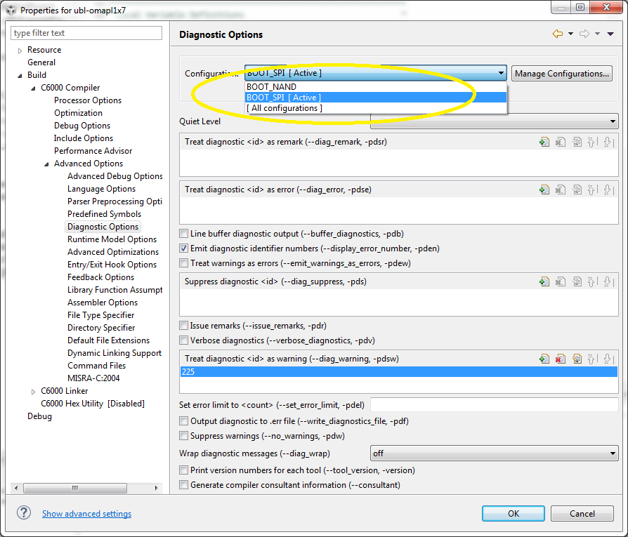
    Set active the "BOOT_SPI" as make configuration.

    Erase the SPI flash, set boot mode to SPI and run the DSP UBL code using CCS, checkout the UART console (you have to change the UART code if you used different console port on your custom board)

    dspubl-03.20.00.14.tar.gz

    armubl-03.20.00.14.tar.gz

  •  Screen shot attached.

  • Hi Deepak,

    By any chance, you have the TI released OMAPL137 EVM?

    If yes, On the first hand, try using the CCS and import the TI released DSPUBL with the TI released OMAPL137 EVM.

    Check whether you are able to debug in this setup.

    Once that is through, approach modifying a small piece of code for your custom board and try debugging through CCS.

    Once the DSPUBL is through using the CCS, you can convert it as a binary and flash into memories.

    To learn about the linker command file, please visit,

  • Hi

    Shankari .

    Thanks for your appropriate answer!!!

    I am able to get the DSP code compiling and but when I try using to compile ARM CODE ARM-UBL I get a error stating that rts32.lib not found to building the SPI Image.

    Let me know what could be going wrong .and What is the path for the library that I have to use for the lib rts32.lib file.

    I also have doubt on Creating the ARM-UBL.bin 

    Is the procedure same as DSP for building the image for ARM

    CONFUSED IN THIS BCOZ DSP IS AIS IMAGE

    SHOULD I GIVE THE GENERTAED SPI-UBL.out of ARM  and generate the bin file for ARM in AIS 

    I have followed the some support previously provided

    unable to run DSP UBL on OMAPL137

    and downloaded the ZIP

    5001.1184.ubl_spi_projects.zip PROVIDED

    Waiting for your response

    Thank you

    Deepak R

  • Hi

    For the above rts32.lib If I compile it with CCSV5 I don't get that ERROR but when I try on CCSV6 Hope this library is missing and I get this error.

    let me know how to add this lib file in CCSV6 and

    How to generated the .bin for the  ARM as the output of ARM-UBL is spi-ubl.out

    Thank you

    Deepak R  

  • 
    

    Finally I have got stuck in the xfer function of SPI

    I have configured the the spi properly

    I have taken the reference of SPI writer for configuring the spi1 values of the DSP code As I hope the spi writer functionality and dsp functionality is similar (In the sense that SPI WRITER writes to memory and reads from memory) Same way what ever is written to memory our DSP UBL will be reading and I checked the code he is implementing some similar stuff in code like sending commands for read for flash!

    I have tried default configuration and the configuration that is working for spi writer but not able to come out of the loop that I have attached here I get stuck in that loop

    I am not able to come out of this loop!

    Uint32 SPI_xferOneChar(SPI_InfoHandle hSPIInfo, Uint32 dataOut)
    {
      VUint32 spiflg, spibuf;
      DEVICE_SPIRegs *SPI = (DEVICE_SPIRegs *) hSPIInfo->regs;

      Uint32 mask = (0x1 << hSPIInfo->config->charLen) - 1;

      // Write output data
      SPI->SPIDAT0 = dataOut & mask;

      do
      {
        spiflg = SPI->SPIFLG;
        if (spiflg & SPI_RXINTFLAG)
        {
          spibuf = (SPI->SPIBUF);
          break;
        }
        if (spiflg & SPI_OVRNINTFLG)
        {
          spibuf = (SPI->SPIBUF);
          SPI->SPIFLG &= SPI_OVRNINTFLG;
          continue;
        }
        if (spiflg & SPI_BITERRFLG)
        {                     
          spibuf = 0x0;
          break;
        }
      }
      while (TRUE);

      return (spibuf & mask);
    }

    Any suggestion required ! Hope if this issue is solved I would be able to get the ARm and uboot!

    Thank you

    Deepak R

  • Hi

    Team

    I got to know the cause of the spi loop get hanged it bcoz the BASE address offset provided in the default code is w.r.t for OMAPL137. I changed the base address w.r.t to data sheet for SPI1

    But now the issue is when I try reading the values from the spi buf in inline debugging I always frequently the value as 7F and the data /COMMANDs that is sent for reading the spi flash is seen in the SPIDAT0 register but the SPIBUF register is not consistent in reading the data ending up to get 7F !

    Kindly let me know what changes to be done!

    As per the SPI I have changed the configuration in the tool for SPI where all the SPI files gets enabled. but not sure where others headers #define has to be enabled in the tool EX FOR UART enabling

    Need your support on this ASAP and SPI CAHNGING

    Thank you

    Deepak R