This thread has been locked.

If you have a related question, please click the "Ask a related question" button in the top right corner. The newly created question will be automatically linked to this question.

OMAP-L138: McBSP Tx lockup

Part Number: OMAP-L138

Hello all,

I'm using the OMAP-L138 with the C674x DSP. McBSP interfaces to the EDMA through a FIFO. Under normal operation my application is working fine and it will frequently stop and start the EDMA and McBSP. The serial port is configured to use an external FSX and CLKX. The lockup appears to always happen once the serial port is started, not in the middle of operation, so the failure could occur in the shutting down of the serial port previously or the re-initialization and startup of when the failure occurred.

In order to get the lockup to occur much more regularly, I have provided an excessively noisy clock to the McBSP and observe the same symptoms to the original lockup (described below). I have had problems with the device that is providing the clocks to be unreliable at times (I have had issues in the past with the clocks disappearing). I understand that having a bad clock is a cause for problems, but I guess I would like to know more specifically about how this problem occurs and what the symptoms can be. The device providing the clocks is 3rd party, so it is essentially another black box for me.

After a lockup has occurred I've investigated the registers to get some idea of what might be going wrong. The EDMA has no Interrupt Pending (IPR) for the McBSP Tx event, EMR and SER are both clear. The EDMA is pointing at the 65th element, which is the next element to be loaded into the FIFO, this is somewhere in the middle of the EDMA paramset. The FIFO appears to be full (length 64). The Mcbsp0DSP.SPCR is 0x02032007 (the McBSP receiver is in use and still functioning) which shows:

  • XRDY is '1-YES'
  • XEMPTY is '0-YES'
  • XRST is enabled
  • XSYNCERR is '0-NO'.
  • XINTM is '00-XRDY'

I read this as meaning the McBSP believes it has sent DXR (which has been set to the first element the EDMA transferred) since it believes it is empty and ready for new data in DXR. As an experiment in my emulator I toggled XRST to disable and re-enable the McBSP. I saw DXR update to my expected element #2, XRDY and XEMPTY were in the same state as above. The FIFO remained full and the EDMA had incremented one position to point to the 66th element. The serial port still remained locked on [now] the 2nd element. It appears like the entire "chain" is still working, so I suspect the problem does not lie in the EDMA or FIFO. I have also physically monitored the DXR pin for activity and see no activity (constant zero). Even after toggling XRST I see no activity on the DXR pin (not even a single transfer) even though I would expect the McBSP to constantly transfer the contents of DXR even when it thinks it has underflow (FREE = '1 - ENABLE').

So the second part of this post is I am looking for a way to recover from this condition. Performing a soft reset (reloading C674x code) does not recover, the next time I start the serial port the same symptoms exist. This restarting of the DSP application follows the McBSP initialization procedure from the User's Guide very closely. The only way I have found to recover is by powering the entire module off with a hard reset. I have attempted to use the PSC to disable and re-enable the McBSP0 after getting in this condition, but no matter what state I try to transition to, PSTAT remains '1 - IN TRANSITION' as if it is not receiving any sort of communication from the McBSP0. Then if I attempt to read any McBSP0 registers, my core hangs and debugging terminates and the only recovery is again the hard power down reset.

So I'm looking for answers to 2 questions:

1) What exactly is locked up and how does it get into this state?

2) Is there any sort of recovery mechanism besides powering off the module?

Thanks for your time,

Marshall

  • Hi Marshall,

    I'm looking into this. I will get back to this thread with my feedback.

    Best Regards,
    Yordan
  • Hi Paul
    From your summary it would appear that it is likely the McBSP state machine that is not responding , more so as it seems like trying to do a local reset/enable/disable via PSC for McBSP module is not working, this typically happens if there is some portion of the module state machine that is still active, therefore it will not acknowledge the "clock stop" requested issued by PSC.

    It does appear that the EDMA CC/TC is fine, it would be good to double check the status registers like CCSTAT/TCSTAT etc.

    It is hard to say what is causing a lock up. From your email looks like you are follwing the initialization sequence listed in section 26.2.12.1 for the McBSP initialization - it has all sorts of additional considerations/ clock cycles needed when using external clocks/frame syncs etc - please make sure that these are followed by the book.

    You want to probe the lines to see what is the difference between the passing vs failing scenario , when you do a restart etc.

    I am not keen on providing recovery mechanisms, without understanding the root cause of what is happening in your system that is causing the lock up...
    however there are potentially few other ways to do a software initiated reset , although none that i would typically suggest
    1) you could try PLLC0 RSTCTRL , that is a software initiated reset , that may essentially reset the entire chip logic.
    2) on McBSP, you could potentially try to follow all the steps listed in 26.2.15 Power Management section , these are for graceful power management shut down of the module, and goes through a bunch of steps that ensure that there is no pending activity in teh state machine - this may not work if the state machine is hung.
    3) you can write to bit 31 in the PSC.MDCTLn register for the McBSP, this is a force bit along with the disable/enable etc, as the note in the description says , we don't usually recommend writing to this bit unless or otherwise specified, essentially this bit will override any clock stop request that is not getting acknowledged by the peripheral and brute force enforce the psc transition - this is typically not recommended as it is expected that you would want to honor not trying to change the power/clock state of the module if it has some portion of its logic that is still active or pending some transfers...

    Hope this helps some.
    Regards
    Mukul
  • Thanks for the detailed reply Mukul. Today I worked through a lot of your suggestion and I'd like to share my results as well as hopefully add some more detail in some areas.

    From your summary it would appear that it is likely the McBSP state machine that is not responding , more so as it seems like trying to do a local reset/enable/disable via PSC for McBSP module is not working, this typically happens if there is some portion of the module state machine that is still active, therefore it will not acknowledge the "clock stop" requested issued by PSC. 

    I agree, it feels like the PSC and McBSP are failing some handshaking which is causing the PSC to "hang" when attempting to shut the McBSP down. I have attempted all 3 shutdown states: SwRstDisable, SyncReset, Disable. All three states had the same symptoms described previously where PSTAT remains 0x1. I'd like to add that while in this state (PSTAT = 0x1) I have the debugger connected and if I attempt to read a McBSP register I get nonstop errors about device core hung until I power on reset the device.

    It does appear that the EDMA CC/TC is fine, it would be good to double check the status registers like CCSTAT/TCSTAT etc. 

    Good idea, I missed these status registers. I checked these registers in normal operation and after the lockup. Nothing stands out when locked up, everything looks idle.

    It is hard to say what is causing a lock up. From your email looks like you are follwing the initialization sequence listed in section 26.2.12.1 for the McBSP initialization - it has all sorts of additional considerations/ clock cycles needed when using external clocks/frame syncs etc - please make sure that these are followed by the book. 

    Yes, I try to follow this procedure as closely as possible. I've checked and rechecked this procedure a couple times. I've noticed there are two procedures listed in spruhh0: 2.12.2.2 and 2.12.1. I am following 2.12.2.2 (external FSXM), but the two look almost identical but the additional step to wait for a FSX edge (which I do). I do have a "two cycle wait" in the appropriate spots - this is simply just a timed wait based on clock speed, I don't actually look for clock edges (so this can't be shortened by a bad clock). In addition, there is actually quite a bit of "other processing" at this step that will add to our wait time, I think I am waiting plenty long enough but if you think this warrants further review (or if a delay between steps 3 and 6 in Procedure 2-2 is bad), I can certainly revisit.

    You want to probe the lines to see what is the difference between the passing vs failing scenario , when you do a restart etc. 

    I sort of hinted at this before, I have looked at them and if needed I can provide scope captures. In the locked up state, the data transmit pin is logic low forever even when DXR is nonzero. I would have expected it to continually push out DXR even when XRDY was set, but I guess it is just not doing anything.

    I am not keen on providing recovery mechanisms, without understanding the root cause of what is happening in your system that is causing the lock up...
    however there are potentially few other ways to do a software initiated reset , although none that i would typically suggest

    Me too, but I appreciate you listing the options. We have a customer seeing the issue and any recovery that is possible would be a great help as the customer would not have to power reset the device. I still plan on continuing to find a root cause for the problem even after I create a recovery mechanism.

    1) you could try PLLC0 RSTCTRL , that is a software initiated reset , that may essentially reset the entire chip logic.

    I tried this and it certainly worked in providing a software reset to the device. After the reset I couldn't connect with my debugger (in reset) or any other method. The device appeared stuck in reset and I wasn't sure how to get it out of reset once this method was triggered. I didn't look much further. Is there some special step I am missing that helps us get out of reset?

    2) on McBSP, you could potentially try to follow all the steps listed in 26.2.15 Power Management section , these are for graceful power management shut down of the module, and goes through a bunch of steps that ensure that there is no pending activity in teh state machine - this may not work if the state machine is hung. 

    I followed these steps to put the McBSP in low power mode prior to shtudown. You were right, I was having problems. Everything goes smoothly until step 5/6/7. I wrote a dummy value to DXR and I never saw XRDY clear to '0'. Wrote a second dummy value and XRDY remained '1'. This reminded me that even in the locked up state (without performing steps 1-4 in 2.15 Power Management) I can write to DXR and never see XRDY clear. Maybe this is a hint as to how the McBSP is locked up.

    3) you can write to bit 31 in the PSC.MDCTLn register for the McBSP, this is a force bit along with the disable/enable etc, as the note in the description says , we don't usually recommend writing to this bit unless or otherwise specified, essentially this bit will override any clock stop request that is not getting acknowledged by the peripheral and brute force enforce the psc transition - this is typically not recommended as it is expected that you would want to honor not trying to change the power/clock state of the module if it has some portion of its logic that is still active or pending some transfers... 

    Well, I know you're not going to like hearing this - but this successfully recovered from this lockup. I was able to "FORCE" the McBSP to shutdown, reload DSP code and the McBSP began executing normally again without a power off reset. I'm planning on moving on with this as our recovery mechanism for the customer now before continuing to root cause this issue. 

    One question I have - what reset mode should I use? SwRstDisable, SyncReset, or Disable? Is there one that is "safer" than the others? One that is "more complete"? I'm planning on setting up this recovery mechanism to detect if the McBSP is in this condition at bootup, so I'm thinking I should then force it to whatever state it is in on reset to keep states as consistent as possible.

     Also, I am planning on trying to do a "not forced" reset to the McBSP first (since TI does not suggest using the FORCE bit). Do you have a suggestion for how long I should wait for PSTAT to clear before doing a FORCE reset?

    //edit

    I also assume I should wait for PSTAT = 0x0 after a forced reset before continuing on?

    Thanks,

    Marshall

  • Hi Marshall

    Thanks for running the experiments and sharing your detailed observations.
    I have to admit that I have limited expertise on McBSP , but it is likely that there is limited expertise on McBSP in general :), so I will (for now) focus on responding to your recovery mechanism (looks like you and i are aligned that this is temporary solution to get your end customer moving and we should still figure out root cause).

    On you query on use for force bit , I would say you can use SwRstDisable, as this both disables/enables the locks and asserts/deasserts local reset to the module. The documentation will mention that both SyncReset and SwRstDisable is not expected to be initiated in software , but so is the use of force bit :).

    It is hard to say how many cycles you should wait for PTSTAT clear, it should not be not be more than couple of 100's cycle, i think as a read to PSC register space maybe worst case 30-40 cycles (or lower) and assuming a few read loops prior to time out - in general PTSTAT should immediately transition , if the module was in good health.

    on PLL initiated reset , that should've worked, but yes it is equivalent of a warm reset, so you will loose connection to jtag and will need to reestablish and likely will be going through a boot again ( in non emulation mode).

    You also obviously have the choice of setting up the on chip watch dog timer to trip after a certain time.

    Overall force bit with mcbsp seems like a localized way that is getting you the desired recovery, so you should be able to stick with it.

    Will parse through your mcbsp portion of the info later.

    regards
    Mukul
  • Mukul -

    I've got the recovery mechanism implemented, tested and to the end customer this week. Thank you for your insight in giving this option and how I should be using it.

    I've also started work on tracking down what seems to be causing this issue. Some of this may be review:

    Using a noisy source for the bit clock: I see the lockup more often when I start/stop the serial port, as opposed to leaving the serial port running continuously. This makes me believe something during the initialization procedure of McBSP is sensitive to the bit clock.

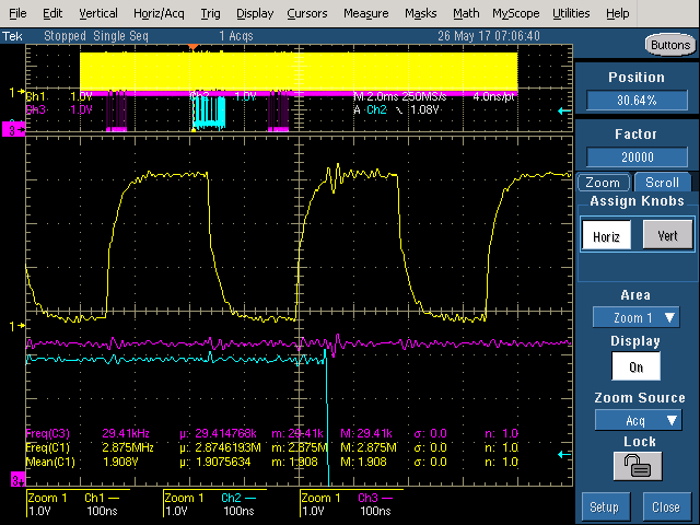
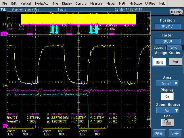
    So I refocused on attempting to find out how our [external] clocks might be noisy or unreliable. I ended up finding a potential crosstalk problem with the usage of another serial port. Obviously this is not TI's problem and I am looking into solutions. I've attached an example screenshot showing the crosstalk, do you agree this looks bad enough to cause a problem? Yellow is the bitclock, blue is the serial port in question tx, purple is the serial port in question rx.

    I'm also curious to know what part of the McBSP initialization procedure is sensitive to the clocks, it might help to create a test that can reliably reproduce the lockup. Is there a certain step that requires a nice stable clock before proceeding?

    Thanks,

    Marshall

  • Hi Marshall
    I will look through the thread again to see if there is more clues to chew on.
    I am also going to cc who has championed several such issues - and may have more guidance.


    It would be good to understand, when you say it only happens during start/stop serial port, what exactly does that mean in terms of device state, and the how the external clock and frame syncs etc are managed during the start and stop.

    The TRM also talks about use of GPIO etc - are you doing that?


    26.2.12.2.1 How to Detect First Frame Sync
    Although the McBSP is capable of generating an interrupt to the CPU upon the detection of frame
    synchronization (XINTM = 2h and/or RINTM = 2h in the serial port control register (SPCR)), the McBSP
    requires the associated portion (receiver/transmitter) of the McBSP to be out of reset in order for the
    interrupt to be generated. Therefore, instead of directly using the McBSP interrupt to detect the first frame
    sync, you can use the GPIO peripheral. This can be achieved by connecting the frame sync signal to a
    GPIO pin. Software can either poll the GPIO pin to detect the first frame sync or program the GPIO
    peripheral to generate an interrupt to the CPU upon detecting the first frame sync edge. For more
    information on the GPIO peripheral, see the General-Purpose Input/Output (GPIO) chapter.
    The following are some recommended GPIO pin(s) on the device that you can use to detect the first
    McBSP external frame sync:
    • GPIO pin located near the McBSP pins. Connect the external frame sync to both the McBSP
    FSX/FSR pin(s) and the dedicated GPIO pin.
    • GPIO pin multiplexed with the McBSP FSX signal. Note that on the device, the GPIO pins (of the
    GPIO peripheral) are multiplexed with the McBSP pins. Software can program the device's pin
    multiplexing register (PINMUX) to default these pins to the GPIO function, and only switch them to the
    McBSP function upon detecting the first frame sync. This method is only recommended if the external
    device is both the frame sync and clock master; that is, the external device drives both the FSX and
    CLKX signals. This method is not recommended if the McBSP is the clock master (driving CLKX
    and/or CLKR), as the “on-the-fly” pin multiplexed switching can cause a glitch on the CLKX/CLKR pin.
    For more details on pin multiplexing, see the device-specific data manual.
  • The external clocks should persist forever while power is supplied. So I am dynamically starting and stopping the McBSP while the clocks continue to tick. The GPIO polling mechanism (described in further detail below) should help me start in a "nice" spot.

    My process for stopping the transmit serializer:

    1. Clear SPCR->XRST (DISABLED).
    2. Clear WFIFOCTL->WENA (DISABLED).
    3. Stop EDMA3
      1. Disable Mcbsp0Tx event (EECR)
      2. Clear Mcbsp0Tx event (ECR)
      3. Disable Interrupt (IECR)
      4. Clear Interrupt (ICR)

    My process for restarting the transmit serializer (this process is done every time I start the McBSP):

    1. Stop EDMA3 (same method as above)
    2. Enable module in PSC. This is done every time I start the transmit serializer even though we never turn the module off after initial bootup. It is during bootup that I implemented the aforementioned recovery mechanism, I attempt to put the PSC in SWRSTDISABLE state, if the command timeouts, I use the FORCE bit to force a PSC transition to SWRSTDISABLE which "recovers" us from the locked up state.
    3. Configure McBSP pins as McBSP.
    4. Clear SPCR->XRST
    5. Clear WFIFOCTL->WENA
    6. Generic McBSP configuration (SPCR, XCR, PCR, XCEREn, WFIFOCTL)
    7. There will be a period of time here while the EDMA3 buffers fill with data prior to kicking everything off. This means EDMA3 parmsets are being loaded.
    8. After EDMA3 buffers are full, wait two clock cycles (this is a hard wait based off the timer, I do not poll the clock edges here)
    9. Set SPCR->XRST (ENABLED)
    10. Wait two clock cycles (same as step #8, not polling clock edges)
    11. Clear SPCR->XRST (DISABLED)
    12. Clear WFIFOCTL->WENA
    13. Start EDMA3
      1. Load final parmset
      2. Enable interrupt
      3. Clear missed event register
      4. Clear secondary event register
      5. Enable event
    14. Set FSX0 as GPIO
    15. Wait for FSX0 falling edge (FSXP is configured 'ACTIVE_HIGH', CLKXP is configured 'FALLING')
    16. Set WFIFOCTL->WENA (ENABLED)
    17. Set SPCR->XRST (ENABLED)
    18. Set FSX0 as FSX0 (McBSP function)

    Just to be clear and address your question about using GPIO polling: Yes, I am waiting for the first FSX edge before turning on the McBSP. The last bullet point in 26.2.12.2.1 is how I do it (by using the device's multiplexer to switch to GPIO and back to McBSP function). Both FSX and CLKX are externally sourced. I followed the initialization procedure in 2.12.2.2 which has steps for using the GPIO to poll for the FSX edge. This was actually added to fix another issue awhile back!

    Thanks and have a good weekend!

  • Marshall Schiring said:
    • Stop EDMA3 (same method as above)
    • Enable module in PSC. This is done every time I start the transmit serializer even though we never turn the module off after initial bootup. It is during bootup that I implemented the aforementioned recovery mechanism, I attempt to put the PSC in SWRSTDISABLE state, if the command timeouts, I use the FORCE bit to force a PSC transition to SWRSTDISABLE which "recovers" us from the locked up state.

    I suggest that you try an experiment where you incorporate the SWRSTDISABLE state into your standard initialization procedure.  In particular, in the second step you show above, first change the McBSP to a disabled stated.  You'll need the ability to timeout if it takes too long and utilize the "force" bit if necessary.  You should print a message in the scenario where the "force" bit is required.

    I'd be interested to understand whether implementing this sort of change fully eliminates any lockups, or if it improves things (and roughly how much).

  • Brad -

    I tried your experiment by putting the SWRSTDISABLE method before step 2 in the standard initialization procedure. I was no longer observing a lockup condition. However, I don't think this is desirable, as I am using the receiver side of Mcbsp0 - so I don't want to potentially be putting the Mcbsp in a disabled/reset state while the receiver is in use. While I did not see the lockup condition, I did see my error message which alerts me that I used the force bit to disable the Mcbsp. This suggests the conditions were still present that locks up the serial port (it does not ACK the PSC disable command), but we will force a recovery to ensure transmit will eventually start. This has me thinking that perhaps the lockup occurs when I disable the serial port rather than during the initialization procedure. Do you agree with this assessment? I can try to take a closer look at the shutdown procedure tomorrow, but I think it is pretty straightforward.

    I do think what I am doing in step 2 is a little weird. I do not think I should enable the Mcbsp each time I go to turn on the serial port - one time at startup should be enough. I tried code that does this and did still receive a lockup. That should eliminate any questions on if enabling an already enabled module would cause this lockup.

    Marshall

  • We need to look more closely at your procedure for disabling the transmitter. First, can you tell me whether the McBSP is driving the CLKX and FSX signals, or are those inputs to the McBSP?

  • Brad
    Thanks for the help on this.
    As per earlier post from Marshall "The serial port is configured to use an external FSX and CLKX. "
  • Oops, thanks. Do these external signals remain on all the time? Or do they stop at some point?
  • From another post

    "The external clocks should persist forever while power is supplied. So I am dynamically starting and stopping the McBSP while the clocks continue to tick. The GPIO polling mechanism (described in further detail below) should help me start in a "nice" spot."

    However I agree that it would be nice for Marshall to reconfirm this.

  • Instead of dynamically stopping/starting the McBSP, can you configure the EDMA to send a buffer of zeros indefinitely during the "off" time?
  • Mukul/Brad -

    Yes, both CLKX and FSX are external to the device. Both clocks are always running.

    I'm not sure if running the serial port forever is an option or not, I will have to look at it more. I know there can be EDMA3 parmset changes between uses which probably isn't too big of a deal, but more importantly I need the transmit and receive synced sometimes.

    The stop procedure is pretty straightforward:

    1. SPCR->XRST to DISABLED
    2. WFIFOCTL->WENA to DISABLED
    3. EDMA3 stop
      1. Disable event
      2. clear event
      3. disable interrupt
      4. clear interrupt

  • I suspect your issue relates to chapter 26.2.15 "Power Management" of the TRM. It mentions the following:

    "In order for the McBSP to be placed in power-down mode by the PSC, ensure that the XRDY and RRDY
    flags in the serial port control register (SPCR) are cleared"

    At a bare minimum, I believe that relates to why you need to use "force" with the PSC. However, I wonder if it actually goes further than that and relates to the lockup itself.

    So first, I note in your original post that you saw XRDY=1 in the failed case. That seems to be directly related to what's being discussed above. Furthermore, there's a detailed procedure listed in 26.2.15 for clearing this condition. Now that said, we will likely want to *try* to make some small modifications in order to leave the receiver side functioning. However, I think the goal should be to have XRDY cleared.

    Perhaps before you even begin that whole process, it might be useful to simply print the value of XRDY (or better yet the entire SPCR) each time you stop the McBSP transmitter. I'm interested to see if there's any correlation between the SPCR value and the lockups, e.g. is XRDY always 1 when you lockup?
  • Hi Brad,

    Good observation, the fact that XRDY is set might be why I can't disable the McBSP module with the PSC. The other theory I had was that there might be some sort of handshake or acknowledge between the PSC and McBSP before shutting down, and because the McBSP appears to be locked up it might not be sending the appropriate ack so the PSC->PSTAT hangs. One of Mukul's suggestions actually mentioned going through the "graceful" shutdown outlined in section 2.15. Below is my response to attempting this procedure (Mukul in red, Marshall in black).

    2) on McBSP, you could potentially try to follow all the steps listed in 26.2.15 Power Management section , these are for graceful power management shut down of the module, and goes through a bunch of steps that ensure that there is no pending activity in teh state machine - this may not work if the state machine is hung.

    I followed these steps to put the McBSP in low power mode prior to shtudown. You were right, I was having problems. Everything goes smoothly until step 5/6/7. I wrote a dummy value to DXR and I never saw XRDY clear to '0'. Wrote a second dummy value and XRDY remained '1'. This reminded me that even in the locked up state (without performing steps 1-4 in 2.15 Power Management) I can write to DXR and never see XRDY clear. Maybe this is a hint as to how the McBSP is locked up.

    In short, the writing of the dummy value to DXR does not clear XRDY.

    I do have a method that I made to dump relevant register values. I used this to verify the issue seen in the field was the same as I saw on my bench. In every single case I have seen this lockup, XRDY has been set (and XEMPTY has been cleared).

    *** C6000 Register Dump ***

    EDMA3 Registers
    EMR: 0x00000000
    ER: 0x0C000C00
    EER: 0x0000C00C
    SER: 0x00008000
    IER: 0x000C000C
    IPR: 0x00000000

    EDMA3 Parmset McBSP0_Tx
    CCNT: 0x000014D7

    Write FIFO Registers
    WFIFOCTL: 0x00010101
    WFIFOSTS: 0x00000040

    McBSP0 Registers
    SPCR: 0x02032001
    -->SPCR Tx: 0x03
    DXR: 0x00010000
    XCR: 0x000400A0

  • Marshall Schiring said:
    I followed these steps to put the McBSP in low power mode prior to shtudown. You were right, I was having problems. Everything goes smoothly until step 5/6/7. I wrote a dummy value to DXR and I never saw XRDY clear to '0'. Wrote a second dummy value and XRDY remained '1'. This reminded me that even in the locked up state (without performing steps 1-4 in 2.15 Power Management) I can write to DXR and never see XRDY clear.

    Was the FIFO disabled at this point?  Would you mind sharing your precise code that implements these steps for review?  One minor coding mistake could be the difference between this working or not working.

    Marshall Schiring said:
    In every single case I have seen this lockup, XRDY has been set (and XEMPTY has been cleared).

    Can you tell me more about the cases where you didn't have the lockup?  Is XRDY clear for all of those?  Or do you get a mix of it sometimes set and sometimes clear?

  • Brad Griffis said:
    Was the FIFO disabled at this point?  Would you mind sharing your precise code that implements these steps for review?  One minor coding mistake could be the difference between this working or not working.

    Yes, the FIFO was disabled in step 1. Below is the code with my comments interleaved. Pretty much run this right at bootup, so I can reproduce the lockup, reload DSP and run this "low power shutdown" immediately. I also shutdown McbspRx in this example even though that is undesired for the final product just to follow the instructions more completely.

        //step 1
        Peripherals.Mcbsp->ResetAll(MCBSP::MCBSP0);
        Peripherals.Edma->Stop(EDMA3::MCBSP0_TRANSMIT);
        Mcbsp0Rx.StopEdma(*Peripherals.Edma);
        this->Peripherals.Mcbsp->PscDisable(MCBSP::MCBSP0);

    void MCBSP::ResetAll(MCBSP::MCBSP_DEVICE Device) { CSL_FINST(McBspRegister[Device]->SPCR, MCBSP_SPCR_XRST, DISABLE); CSL_FINST(McBspRegister[Device]->SPCR, MCBSP_SPCR_RRST, DISABLE); CSL_FINST(McBspRegister[Device]->SPCR, MCBSP_SPCR_FRST, RESET); CSL_FINST(McBspRegister[Device]->SPCR, MCBSP_SPCR_GRST, RESET); CSL_FINST(FifoRegister[Device]->RFIFOCTL, BFIFO_RFIFOCTL_RENA, DISABLED); CSL_FINST(FifoRegister[Device]->WFIFOCTL, BFIFO_WFIFOCTL_WENA, DISABLED); }
    void EDMA3::Stop(enum EVENT Event)
    {
        DisableEvent(Event);
        ClearEvent(Event);
        DisableInterrupt(Event);
        ClearInterrupt(Event);
        Irq[Event].Function = NULL;
    }

    Simply writing to the shadow EECR, ECR, IECR, ICR. Same process for Edma3Tx and Edma3Rx.

    The meat of the process:

    void MCBSP::PscDisable(MCBSP::MCBSP_DEVICE Device)
    {
        uint32_t RRDY;
        uint32_t DRR;
        switch (Device)
        {
            case MCBSP0:
                //Step 1 completed previously
    
                //Step 2 Switch the McBSP clocks and Frames to internal clock source
                //2a
                CSL_FINST(McBspRegister[Device]->SRGR, MCBSP_SRGR_CLKSM,     INTERNAL);
                CSL_FINST(McBspRegister[Device]->SRGR, MCBSP_SRGR_FSGM,      FSG);
                //2b
                CSL_FINST(McBspRegister[Device]->PCR, MCBSP_PCR_CLKXM,       OUTPUT);
                CSL_FINST(McBspRegister[Device]->PCR, MCBSP_PCR_CLKRM,       OUTPUT);
                CSL_FINST(McBspRegister[Device]->PCR, MCBSP_PCR_FSXM,        INTERNAL);
                CSL_FINST(McBspRegister[Device]->PCR, MCBSP_PCR_FSRM,        INTERNAL);
                //2c
                CSL_FINST(McBspRegister[Device]->PCR, MCBSP_PCR_SCLKME,      NO);
    
                //Step 3 Bring the McBSP out of reset
                CSL_FINST(McBspRegister[Device]->SPCR, MCBSP_SPCR_XRST, ENABLE);
                CSL_FINST(McBspRegister[Device]->SPCR, MCBSP_SPCR_RRST, ENABLE);
                CSL_FINST(McBspRegister[Device]->SPCR, MCBSP_SPCR_GRST, CLKG);
    
                //Step 4 Wait two CLKSRG cycles (10 microsecond wait here)
                WaitForTwoClockCycles();
    
                //Step 5 Write dummy value to DXR
                McBspRegister[Device]->DXR = 0xA5A5A5A5;
    
                //Step 6 Wait one McBSP bit clock (10 microsecond wait here)
                WaitForTwoClockCycles();
    
                //Step 7 Write second dummy value to DXR
                McBspRegister[Device]->DXR = 0x5A5A5A5A;
    
                //Step 8 Check RRDY, read DRR if set
                RRDY = CSL_FEXT(McBspRegister[Device]->SPCR, MCBSP_SPCR_RRDY);
                if (RRDY == 1)
                {
                    DRR = McBspRegister[Device]->DRR;
                }
    
                //Step 9 Power down McBSP
                Psc.DisableMcBsp0();
                break;
    
            case MCBSP1:
                Psc.DisableMcBsp1();
                break;
    
            default:
                break;
        }
    }

    DisableMcbsp0() goes through the process of reading PSTAT, setting MDCTL and PTCMD and rereading PSTAT. That method is pretty hacked up at the moment because of my addition of timeouts, error messages, and usage of the force bit. It's in here where it will timeout and require the force bit anyways. After the two dummy writes I never see XRDY get cleared.

    Brad Griffis said:
    Can you tell me more about the cases where you didn't have the lockup?  Is XRDY clear for all of those?  Or do you get a mix of it sometimes set and sometimes clear?

    Cases where I don't have a lockup would just mean the normal steady state? XRDY appears to be clear for all these, but I assume there is a very small amount of time where it is set until the WFIFO fills DXR and clears XRDY again. It would seem to be very hard or unlikely to see XRDY set in normal operation.

    To your comments I spent some time today developing a test that would only shut off the McBSP when XRDY is set to see if this might cause a problem. The most successful and convincing test I came up with was shutting off the EDMA3 first and letting the WFIFO run dry assuring XRDY was set before clearing XRST and WFIFOCTL->WENA. I let this order of shutdown run for a few hours and saw no lockups. As an aside, I did try first to disable the WFIFO (to starve DXR), but I was seeing some curious behavior. I couldn't get XRDY to "stay" set. I have a while loop waiting for XRDY to be set, and by the time i exit the while loop and reread SPCR, XRDY would be cleared again no matter how long I waited after disabling the WFIFO. Just an observation, not sure if it matters but it seems the WFIFO and McBSP are closely linked and I probably shouldn't mess with this order of shutdown.