This thread has been locked.

If you have a related question, please click the "Ask a related question" button in the top right corner. The newly created question will be automatically linked to this question.

OMAPL138B-EP: OMAPL138 Interfacing to ST7735S TFT LCD using 8080

Part Number: OMAPL138B-EP
Other Parts Discussed in Thread: OMAPL138, OMAP-L138

Hi,

I noticed that in theory, it is possible to interface TFT LCD ST7735S using 8-bit Intel 8080 interface via the LIDD controller. Is there something else I need to check to make sure that this interface will work smoothly? Is there any other parameter I need to check on either datasheet?

Thanks

  • The team is notified. They will post their feedback directly here.

    BR
    Tsvetolin Shulev
  • Hi
    I have moved this post to the OMAPL1x forum, as I think you accidentally used OMAPL138-EP , "EP" is Enhanced Product and ends up going to our high reliability team.
    If you are looking to post questions on OMAPL138 regular product offerings (not the enhanced /hi rel version), you can use OMAP-L138 in the Part Number box , while creating a new post so that it gets routed to the proper product team.


    Regards
    Mukul
  • Hi Mukul,

    Thanks! I was also wondering if you could give me any feedback on my original question about using 8080 mode to interface TFT LCD using the LIDD LCDC.

  • Hi
    I have assigned it to the LCD owners to take a look, from my quick review it should work as it seems to be just following 8080 , which is supported by the on chip LCD module in LIDD mode.
    We will get back to you if we see anything missing.

    Do note that we do not have any drivers or reference code in Processor SDK for the LIDD mode and I also checked older software releases listed here
    processors.wiki.ti.com/.../OMAPL138_SW_&_HW_Comparison
    However I am hoping this should be straightforward to implement.

    Regards
    Mukul
  • Hi Mukul,

    Thanks for your quick reply. Under Starterware, I'm seeing the old EVM have an example for LIDD
    \ti\OMAPL138_StarterWare_1_10_04_01\examples\evmOMAPL138\lidd

    I am assuming this can still be used?
  • Hi
    Yes you can use this as reference
    processors.wiki.ti.com/.../StarterWare_01.10.01.01_User_Guide

    Starterware is now provided as is and is no longer supported for updates/fixes, but continues to serve as a good reference for customers to get started if the equivalent coverage does not exist in the proc SDK.

    Part of the reason this example did not make it , is the LIDD LCD showcased here was part an older Logic PD EVM UI daughtercard offering.
    This EVM is no longer available and has been replaced by OMAPL138 LCDK.

    However, it should still be a good reference for an software example.

    Regards
    Mukul
  • Thanks for the clarification. I am trying to quickly prototype a working 8080 interface for a TFT LCD display. I notice that the LCD header on the LCDKOMAPL138 kit is routed through a  video DAC or Dual Voltage Buffer. I am just looking for some clarification if this might work, before running too far down the wrong path. Are the LCDK header usable at all in the 8080 mode - J14 and J15? I am not seeing how I can use the GPIOs as bidirectional to send 8 bit LCD data -(D0-D7). Would appreciate your input.

  • Hmmm. All that video logic might be in the way. U14 has its direction tied from B to A, so it will be difficult to read back from the ST7735 registers.

    Just looking at the data signals for now... You might have to blue-wire from U14 and lift the OE pins and pull-ups. Otherwise, you can get output-only data signals on P1 and P2.

    Or would you rather bit-bang the LCD data out from the GPIOs through J14?

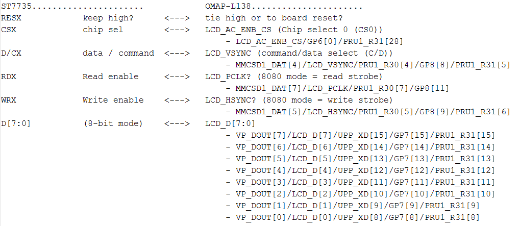
    Is this your desired mapping to between the ST7735 and the OMAP-L138?

    Regards,
    Mark

    [EDIT - fixed spacing with image...]

  • Mark,

    On second thought, using the LCD Bank with the above pin out may be the desired operation.

    Should I just remove U21 and jumper the pins?
    Would P1 and P2 be able to function bidirectionally or just as outputs?
    I can still use one of the I2C buses from J14/15.

    How do I configure the LCD_D[7:0] pins? As GPIOs ?

    Unrelated but is it possible at all to have bidirectional GPIOs? I understand that they might have weak pull ups. How do I configure a pin to be bidirectional?
  • Reminder
  • Hi,

    I'm referring to the OMAP-L138/C6748 LC Dev Kit Ver A7E (www.ti.com/.../sprcaf3.zip).
    Is this the same EVM that you have?

    If you can get by with the data signals as output only, then all the 8080 LCD signals are present at P1/P2 (1.8V IO, which works for ST7735)
    If you must read back from the LCD registers via the data signals, then blue-wiring is required, and they will be at 3.3V IO (at the high end for ST7735)
    LCD_AC_ENB_CS (Chip select 0 (CS0)) @ U12 pin 6 (3.3V IO) (level shifts from B to A)
    LCD_VSYNC (command/data select (C/D)) @ U24 or U15 pin 6 (3.3V IO) (level shifts from B to A)
    LCD_PCLK? (8080 mode = read strobe) @ U12 pin 7 (3.3V IO) (level shifts from B to A)
    LCD_HSYNC? (8080 mode = write strobe) @ U24 or U15 pin 7 (3.3V IO) (level shifts from B to A)
    LCD_D[7:0] or LCD_D[15:0] @ U14 Lift OE pins 25, 48 solder to B side (3.3V IO) - 8-bit or 16-bit mode

    Should I just remove U21 and jumper the pins?
    No, U21 converts analog video input to VPIF video input pins

    Would P1 and P2 be able to function bidirectionally or just as outputs?
    Before the LCD signals arrive at P1/P2, they go through 3.3V to 1.8V level shifters with direction fixed from B to A. So the LCD Data signals are output only at P1/P2.

    I can still use one of the I2C buses from J14/15.
    You can use I2C at 1.8V IO at P1 and P2. Or else wire to the 3.3V side at J15.

    How do I configure the LCD_D[7:0] pins? As GPIOs ?
    You will need to pin mux the LCD signals out of the device to the device pins.
    Refer to 11.5.11 Pin Multiplexing Control Registers (PINMUX0-PINMUX19) in the OMAP-L138 Technical Reference Manual (www.ti.com/.../spruh77c.pdf)
    For example PINMUX16_31_28 should get set to 0x2, to route LCD_D[2] to the pin.
    Then within the LCD peripheral, you will have to configure the LCD to LIDD mode in LCD_CTRL register, and the LIDD mode to Async MPU80 (8080 mode, no clock).

    I would start with a software example.

    Unrelated but is it possible at all to have bidirectional GPIOs? I understand that they might have weak pull ups. How do I configure a pin to be bidirectional?

    Not really. The GPIOs have a direction register, output or input.
    The GPIOs have configurable internal pulls, but their levels are tied together as a group.
    For example CP[28], CP[29], and CP[31] control all pulls on the LCD pins.
    Refer to section Table 3-24. Liquid Crystal Display Controller (LCD) Terminal Functions in the datasheet for the LCD pin to CP mapping
    Also refer to TRM sections 11.5.23 Pullup/Pulldown Enable Register (PUPD_ENA) and 11.5.24 Pullup/Pulldown Select Register (PUPD_SEL)

    Hope this helps,
    Mark
  • Hi,

    Are you still working on this issue? Did the above information help?

    Regards,
    Mark
  • Hi Mark,

    Thanks for your response. We are waiting on a daughter card for the screen. It should be here by mid next week. I'll be sure to mark resolved as soon as I confirm it. Regardless, the resources you provided were extremely valuable. Thanks again.