This thread has been locked.

If you have a related question, please click the "Ask a related question" button in the top right corner. The newly created question will be automatically linked to this question.

EDMA with SPI

Other Parts Discussed in Thread: TMS320C6745, SYSBIOS

Hi ,

I am using TMS320C6745 and trying to use EDMA with SPI_1, but I am unable to get the IPR bit for SPI_1.

I am setting the SPI bit for DMA request enable also

    spiRegs->SPIINT0 |= ( 1 << 16 );    // DMA Request Enabled

I am doing the following setting for EDMA:

  static void setup_EDMA (void)
{
    // Clear Event Registers
    CSL_FINST(edma3ccRegs->ECR, EDMA3CC_ECR_REG, MASK);
    CSL_FINST(edma3ccRegs->SECR, EDMA3CC_SECR_REG, MASK);

    // Enable Channel 18 to DSP (Region 1)
    CSL_FINST(edma3ccRegs->DRA[CSL_EDMA3_REGION_1].DRAE,
                EDMA3CC_DRAE_E18, ENABLE);

    // Assign Channel 18 to Queue 0
    CSL_FINST(edma3ccRegs->DMAQNUM[1], EDMA3CC_DMAQNUM_E2, Q0);

    // Initialize PaRAM Transfer Context for Event 18
    init_PaRAM_event18();

    // Enable Channel 18 Event Register
    CSL_FINST(edma3ccRegs->EESR, EDMA3CC_EESR_E18, SET);

    // Enable Interrupts for Channel 18
    CSL_FINST(edma3ccRegs->IESR, EDMA3CC_IESR_I18, SET);
}/* setup_EDMA */

Please suggest me if any mistake I am doing while the configuration.

Regards,

Arvind

  • Hi Arvind,

    Which Source code you are trying with?
    I think you are referring rCSL based example code.
    ~\quickStartOMAPL1x_rCSL\OMAPL1x\rCSL_examples\evmOMAPL137\DSP_examples\edma\EDMA_event_trig_dspL137
    This example code is for timer, what other changes you have done?
    Have you tried example code as-is, as example code is configuring channel 10 for queue 0.
  • Yes, I am trying with OMAPL137 EDMA Event trigger example.
    I tried the code as it is it worked but now i am trying to make it work with SPI_1 interrupts.

    I changed the timer interrupt with SPI_1 interrupt even in intvecs.asm file i replaced timer with SPI.
    .global _intcVectorTable
    .global _c_int00
    .global _EDMA3CC_INT1_isr
    .global _SPI1_INT_isr

    _vector4: VEC_ENTRY _EDMA3CC_INT1_isr ;DSP Maskable INT4 : Mapped to func 'EDMA3CC_INT1_isr'
    _vector5: VEC_ENTRY _SPI1_INT_isr ;DSP Maskable INT5 : Mapped to func 'SPI1_isr'

    I changed channel 10 to channel 18 since channel 18 is for SPI_1 receive as I am expecting to recieve data on SPI

    static void init_PaRAM_event18 (void)
    {
    // Reset EDMA PaRAM OPT Register
    edma3ccRegs->PARAMSET[EDMA_EVENT18].OPT = CSL_EDMA3CC_OPT_RESETVAL;

    // Config PaRAM OPT (Enable TC Interrupt; Set TCC)
    edma3ccRegs->PARAMSET[EDMA_EVENT18].OPT =
    CSL_FMKT(EDMA3CC_OPT_TCINTEN, ENABLE) |
    CSL_FMKT(EDMA3CC_OPT_ITCINTEN, ENABLE) |
    CSL_FMK(EDMA3CC_OPT_TCC, EDMA_EVENT18);

    // Initialize EDMA Event Src and Dst Addresses
    edma3ccRegs->PARAMSET[EDMA_EVENT18].SRC = (Uint32)spiRegs->SPIBUF;
    edma3ccRegs->PARAMSET[EDMA_EVENT18].DST = (Uint32)&dstBuffer;

    // Set EDMA Event PaRAM A,B,C CNT
    edma3ccRegs->PARAMSET[EDMA_EVENT18].A_B_CNT =
    CSL_FMK(EDMA3CC_A_B_CNT_ACNT, 1) | //CSL_FMK(EDMA3CC_A_B_CNT_ACNT, XFER_BYTES) |
    CSL_FMK(EDMA3CC_A_B_CNT_BCNT, 36); //CSL_FMK(EDMA3CC_A_B_CNT_BCNT, XFER_ARRAYS);

    edma3ccRegs->PARAMSET[EDMA_EVENT18].CCNT = XFER_FRAMES;

    // Set EDMA Event PaRAM SRC/DST BIDX
    edma3ccRegs->PARAMSET[EDMA_EVENT18].SRC_DST_BIDX =
    CSL_FMK(EDMA3CC_SRC_DST_BIDX_SRCBIDX, SRC_ARRAY_SIZE) |
    CSL_FMK(EDMA3CC_SRC_DST_BIDX_DSTBIDX, DST_ARRAY_SIZE);

    // Set EDMA Event PaRAM SRC/DST CIDX
    edma3ccRegs->PARAMSET[EDMA_EVENT18].SRC_DST_CIDX =
    CSL_FMK(EDMA3CC_SRC_DST_CIDX_SRCCIDX, 0) |
    CSL_FMK(EDMA3CC_SRC_DST_CIDX_DSTCIDX, 0);

    // Set EDMA Event PaRAM LINK and BCNTRLD
    edma3ccRegs->PARAMSET[EDMA_EVENT18].LINK_BCNTRLD =
    CSL_FMK(EDMA3CC_LINK_BCNTRLD_LINK, PaRAM_NULL_LINK) |
    CSL_FMK(EDMA3CC_LINK_BCNTRLD_BCNTRLD, 0);
    }/* init_PaRAM_event18 */
  • Hi Arvind,
    So you are configuring EDMA as transmitter and SPI as receiver.
    From EDMA side it looks fine.
    How you have setup SPI in receive mode ?
    Is it in Master mode or Slave mode?
    Have you included cslr_spi.h. header file for CSL API's and memory mapped registers for SPI.
    Check OMAPL137_common.h header file line (200-215), you need to add

    extern CSL_SpiRegsOvly spiRegs;
  • Hi,

    I am expecting data on SPI_1(slave mode), and through EDMA I am trying to store each byte of data from SPIBuffer to another Array (since each byte of data received at SPI should give a event)

    Data is coming to SPI_1 @ 4MHz.

    Yes I have included extern CSL_SpiRegsOvly spiRegs, and also OMAPL137_common.h is included in my header

    SPI_init below:

    void Spi_init(void)
    {
    unsigned int LPSC_num=10, PD=0;

    PINMUX7 = 0x11111111;
    PINMUX8 = 0x11122111;
    PINMUX9 = 0x11011111; // RMII CLK, McASP0, USB_DRVVBUS, UART2

    if( (*(unsigned int*)(PSC1_MDSTAT + 4*LPSC_num) & 0x1F) != 0x3 ) {
    *(unsigned int*) (PSC1_MDCTL+4*LPSC_num) = (*(unsigned int*) (PSC1_MDCTL+4*LPSC_num) & 0xFFFFFFE0) | 0x0003;
    PSC1_PTCMD = 0x1<<PD;

    /*Wait for power state transition to finish*/
    while( (PSC1_PTSTAT & (0x1<<PD) ) !=0) { }

    while( (*(unsigned int*)(PSC1_MDSTAT+4 * LPSC_num) & 0x1F) !=0x3) { }
    }

    CSL_PscRegsOvly psc0Regs = (CSL_PscRegsOvly)CSL_PSC_0_REGS;

    /* deassert SPI0 local PSC reset and set NEXT state to ENABLE */
    psc0Regs->MDCTL[CSL_PSC_SPI0] = CSL_FMKT( PSC_MDCTL_NEXT, ENABLE )
    | CSL_FMKT( PSC_MDCTL_LRST, DEASSERT );
    /* Move SPI0 PSC to Next state */
    psc0Regs->PTCMD = CSL_FMKT( PSC_PTCMD_GO0, SET );

    /* Wait for transition */
    while ( CSL_FEXT( psc0Regs->MDSTAT[CSL_PSC_SPI0], PSC_MDSTAT_STATE )
    != CSL_PSC_MDSTAT_STATE_ENABLE );

    /* First reset the SPI chip */
    spiRegs->SPIGCR0 = CSL_FMK(SPI_SPIGCR0_RESET,
    CSL_SPI_SPIGCR0_RESET_IN_RESET);

    /* now bring the chip out of reset state */
    spiRegs->SPIGCR0 = CSL_FMK(SPI_SPIGCR0_RESET,
    CSL_SPI_SPIGCR0_RESET_OUT_OF_RESET);

    /* Enable the SPI#1 in Slave mode in the SPI global control reg */

    spiRegs->SPIGCR1 = 0
    | ( 0 << 24 )
    | ( 0 << 16 )
    | ( 0 << 1 )
    | ( 0 << 0 );


    /* enable the pins so that they are used for the SPI interface(Multiplex) */

    spiRegs->SPIPC0 = 0
    | ( 1 << 11 )
    | ( 1 << 10 )
    | ( 1 << 9 )
    | ( 1 << 1 )
    | ( 1 << 0 );

    /* configure the data format in SPIFMT */

    spiRegs->SPIFMT[0] = 0
    | ( 0 << 20 ) // SHIFTDIR
    | ( 0 << 17 ) // Polarity
    | ( 1 << 16 ) // Phase
    | ( 4 << 8 ) // Prescale
    | ( 8 << 0 ); // Char Len


    /* set the preconfigure data format as 0 which is already set above */
    spidat1 = 0
    | ( 1 << 28 ) // CSHOLD
    | ( 0 << 24 ) // Format [0]
    | ( 0 << 16 ) // CSNR [only CS0 enbled]
    | ( 0 << 0 ); //

    spiRegs->SPIDAT1 = spidat1 ;

    spiRegs->SPIDELAY = 0
    | ( 8 << 24 ) // C2TDELAY
    | ( 8 << 16 ); // T2CDELAY

    spiRegs->SPIDEF = 0
    | ( 1 << 1 ) // EN1 inactive high
    | ( 1 << 0 ); // EN0 inactive high

    /* dont use any interrupts hence disable them */
    spiRegs->SPIINT0 = 0
    | ( 0 << 16 ) // DMA Request
    | ( 0 << 9 )
    | ( 1 << 8 ) //
    | ( 0 << 6 ) //
    | ( 1 << 4 ); //


    spiRegs->SPILVL = 0
    | ( 1 << 8 ) // EN0 0
    | ( 0 << 6 ) // EN0
    | ( 0 << 4 ); // EN0

    spiRegs->SPIGCR1 |= ( 1 << 24 );

    spiRegs->SPIINT0 |= ( 1 << 16 ); // DMA Request Enabled

    //printf("\nSPI#1 configured in Slave mode.\n");
    }
  • Hi Arvind,

    I am trying to reproduce issue at my end.
    Thanks for your patience, will get back to you.
  • Hi Arvind Singh,
    Any update on the issue, whether you are able to reproduce the issue at your end.
    Waiting for your response.

    Thanks & Regads,
    Arvind Kumar
  • Hi Arvind Singh,

    Did you were able to get the solution?
    This problem is getting a bottle neck for my project.
    Please reply ASAP.

    Thanks & Regards
    Arvind Kumar
  • Hi Arvind,

    Apologies for the delayed response.
    I found a post in which a customer was having same problem as you were having and was resolved.
    Please have have a look at below mentioned link.
    e2e.ti.com/.../329149
  • Hi Arvind Singh,

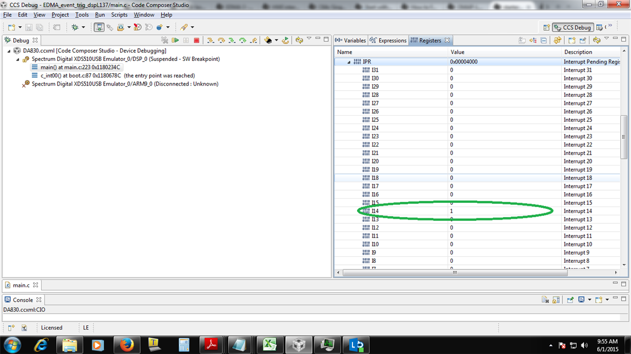
    I have gone through the link you sent, But in my case I am able to set IER & EESR, but I am never getting IPR in my case. Also IESR is always 0 in my case.

    I am not getting any activity on ER for SPI1 (18 bit), even I am getting activity on I2C1(26 & 27) which is not configured.
    For me SPI1 is Slave so I am expecting some activity on Bit 18 of ER register which is not happening.

    Regards,
    Arvind Kumar
  • Hi Arvind,

    Again Apologies for delayed response.

    I have done some experiments on my end. I have configured spi0 as slave.

    I have manually triggered interrupt, IPR is also getting set.


    But Still further improvement has to be done.

    I am attaching project zip file for your reference.

    EDMA_event_trig_dspL137.zip

  • Hi Arvind Singh,

    Thanks for support, i am now getting the interrupts and things are working.

    But few thing want to ask :

    1. for a continuous operation, is it required to call "setup_EDMA()" again. As I observed just calling "init_PaRAM_event14()" is not enough. Please suggest minimum setting for continuous operation.
    2. Is spi_isr() necessary, since we are not doing any operation in this.

    Issue while porting to sysbios:
    1. I am trying to put the same code with SYSBIOS, and I am trying to read the same in a 10ms clock but it seems it stucks in the while loop.
    Help required regarding using the same in a clock function in SYSBIOS.

    Regards,
    Arvind
  • Hi Arvind,


    1. for a continuous operation, is it required to call "setup_EDMA()" again. As I observed just calling "init_PaRAM_event14()" is not enough. Please suggest minimum setting for continuous operation.

    For continuous operation you need to trigger interrupt every-time. That might work fine, but i am not sure.


    2. Is spi_isr() necessary, since we are not doing any operation in this.

    As it is just an example, and we are not doing any thing in spi ISR , but in real time you might need to do some necessary stuff inside isr which much execute quickly and can come out.