This thread has been locked.

If you have a related question, please click the "Ask a related question" button in the top right corner. The newly created question will be automatically linked to this question.

TMS320C6747: multiple DMA channels allocation for 2 ports McASP input and output

Part Number: TMS320C6747

Dear Champs,

My customer requested to know how they can allocate more DMA channels when they will use additional McASP ports for other audio I/O.

e.g. they want to implement receiving audio channels through both of McASP1 and McASP0(AXR0[9]), and transmit it through both of McASP1 and McASP2(DIT).

 Could you please let me know how they can add DMA channels for additional McASP0  and McASP2 processing?

Thanks and Best Regards,

SI.

  • Sung-IL,

    What example code are they using for using DMA channels with McASP1? That would be the best starting point. Or the EDMA code that they are actually using.

    Your customer should also look through the material in the online workshop material in C6000 Embedded Design Workshop. This class includes good information on using the C674x devices, and even though it directly discusses the C6748, the similarities are strong with the C6747. There is a section on using EDMA3.

    Regards,
    RandyP

  • If you are using high level EDMA3 LLD driver then you should be able to use "EDMA3_DRV_requestChannel" API after EDMA_DRV_Open to request additional channel resources. After the channel is allocated then you can set the paramset before initiating a manual or event based transfer.

    If you are not using EDMA Driver but functional CSL then the same can be done using CSL API "EDMA3RequestChannel" after calling into EDMA3Init to request any channel. On this device EDMA channel allocated to peripheral are not fixed so you can request any channel.

    There is an example for MCASP using LLD (pdk_omapl_x_X_X_X/packages/ti/drv/mcasp/example)as well as CSL (pdk_omapl_x_X_X_X/packages/ti/board/diag/mcasp) in the SDK that can be used for reference.

    Regards,
    Rahul
  • Hi Rahul,

    My customer tried to implement it as you recommended on mcasp_audiodc_test.c(\\pdk_omapl13x_1_0_1\packages\ti\board\diag\mcasp_audiodc\src\mcasp_audiodc_test.c), but they found there was discontinuity in audio sound with DMA.
    When they tried to test it without DMA, there was no issue in audio quality.
    Could you please let me know which parameters should be checked in DMA to remove this discontinuity in audio sound?


    Thanks and Best Regards,
    SI.
  • SI,

    The information that you are providing is not sufficient for us to comment on. Please provide the modified code source file and a block diagram of the clocking and the serializers used for us to be able to comment on the topic. Without understanding the configuration, it would be difficult for us to comment on this issue.

    Just to confirm, the original 8 channel audio loopback using audio daughter card is working as expected but only when you add the updated MCASP0 code with DMA, there is discontinuity observed int he audio output.

    Regards,
    Rahul

  • Hi Rahul,

    Unfortunately it is hard for them to provide source code to outside of their company even when it is simple example codes, and all e-mail should be checked with their security.
    This is why they are waiting our examples, and they will modify by themselves referring to our example codes.
    Is there any other scenario using McASP1 and McASP0 on audio daughter card?

    Can you imagine what should be checked for DMA control ?
    Can you image why there is no issue in audio quality without DMA?

    Thanks and Best Regards,
    SI.

  • Sung-IL,

    1. Please confirm, the original 8 channel audio loopback using audio daughter card is working as expected but only when you add the updated MCASP0 code with DMA, there is discontinuity observed int he audio output.

    2. When they do not use DMA, is that for McASP0 only or is the CPU (no DMA) used for the original McASP1 plus the new McASP0?

    3. Please describe the discontinuity. Does it occur for every buffer that is filled, or every N count of buffers, or randomly?

    4. Is the DMA transferring between the McASPs and internal memory or external memory? There can be resource conflicts if all DMA channels are trying to access external memory at the same time. In some situations like this, we have succeeded by transferring directly to/from an internal memory like L2 or SharedRAM, then transfer from that intermediate buffer to the final location separated; this can allow the McASP0/1 accesses to be as quick as possible, then have the buffer transfer occur at a different time when no conflicts would occur.

    5. Do all of the McASPs operate with the same clock rate? With the same Frame Sync rate?

    6. Are the McASPs in sync with each other, meaning they will all be full/empty at the same time?

    7. How fast are the McASPs running, what is their bit clock and frame rate? How fast is the DSP running? How fast is the SDRAM running?

    Which DMA channels are being used?
    Which Transfer Controllers are chosen for each channel?
    What are the Acnt and Bcnt and Ccnt values that are used?
    What are the OPT register values?
    Do any of the channels chain from one to another?

    The audio discontinuities are of course caused by one or more McASPs being serviced too late, causing incoming samples to be lost and/or outgoing samples to be repeated. Normally, it is much easier for the DMA to service a peripheral than for the CPU to do that. But if they have programmed the DMA in such a way that too many resources must be used in a very short amount of time, then problems like this can happen.

    The solution is to figure out what the conflicts are and then to find changes that will remove or minimize those conflicts.

    It is not possible to speculate on every possible problem they could have introduced into the code. If they can answer the questions above, it will give us some clues to consider.

    Regards,
    RandyP
  • Hi RandyP,

    I checked more details and the answers are as below.
    As I said, they enabled McASP0 and DMA for McASP0 in 'mcasp_audiodc_test.c' main function, and mix it with McASP1 input(8ch) by just adding and output it through McASP1 TX.
    e.g.) McASP0 RX(2ch) + McASP1 RX(8ch) --> McASP1 TX(8ch)

    And also, let me correct the kind of noise. it was not discontinuity but distorted noise like causing by overflow. I'm sorry for this my mistake.

    For your questions,
    1. Yes. original 8ch audio still alive.

    2. I found they used different example and used below to test McASP0 without DMA.
    support.spectrumdigital.com/.../DSKDA830_BSL_revf.zip

    In DSKDA830_BSL_revf\dskda830_v1\dsp\tests\audioboard\dc_audio

    dc_audio_test.c


    3. sorry again. it was not discontinuity. it was distorted noise. When there was no audio input source(e.g. unplugged audio input), there was no noise heard.

    4. internal memory only. they do not use external memory now.

    5. they are using same 48khz for McASP0 and McASP1 rx input.

    6. No. they test it on audio DC( www.spectrumdigital.com/.../ ), and I think it was not sync each other in audio DC.

    7. 48kHz I2S input for McASP and 300Mhz CPU clock were used.
    They allocated DMA0 for McASP0 RX, and all others DMA settings were copied from McASP1 except buffer address. no channel chain was used.


    Thanks and Best Regards,
    SI.
  • Sung-IL,

    If all data samples occur at the correct time (no discontinuities) but some data values are incorrect (distortion), then I cannot think of a reason why there would be a difference between DMA access and CPU access. I will not be of much help in this case.

    As an experiment, leave all of the DMA channels running for McASP0 and McASP1 but do not add McASP0 to McASP1. Please confirm whether the distortion occurs in this case using the full code but with data only McASP1 RX(8ch) -> McASP1 TX(8ch).

    As a second experiment, do not use McASP1 RX(8ch) but send copies of McASP0 RX(2ch) to all of McASP1 TX(8ch). Please confirm whether the distortion occurs in this case using the full code but with data only McASP0 RX(2ch) -> McASP1 TX(8ch).

    Those are my only ideas.

    Regards,
    RandyP
  • Hi,

    How about no sync between McASP0 RX and McASP1 TX/RX?
    When I checked AudioDC schematic, it seemed there is no way to sync between McASP0 RX and McASP1 TX/RX. I'm wondering if it is OK to add the audio input of McASP0 and McASP1 although these are not sync each other.

    Do you think this scenario of 'McASP0 RX(2ch) + McASP1 RX(8ch) --> McASP1 TX(8ch) ' is OK even when there was mis-matched synce between McASP0 and McASP1?


    Thanks and Best Regards,
    SI.
  • SI,

    You mentioned that the 8 channel MCASP1 analog code is working independently. Can you also confirm the digital loopback code (MCASP0 RX to MCASP1 TX)with DMA is working independently before integrating into the full implementation. This will help us understand that there is no clock sync issues going on between the digital loopback and the analog loopback that is impacting this implementation. This will be clarified with the experiments that Randy has requested in the previous post.

    We have already discussed the clocking issues with MCASP0 and MCASP1 to run this use case concurrently in offline discussions. How are they handling that issue ?

    Regards,
    Rahul
  • HI Rahul and RandyP,

    I'll check your inquires, but I'm afraid it takes time as he is putting this issue aside and engaging in other work now.

    Thanks and Best Regards,
    SI.
  • Hi Rahul and RandyP,

    To test multiple McASP work, I modified the example of dc_audio_spdif_tone.c file of  'support.spectrumdigital.com/.../DSKDA830_BSL_revf.zip', and found the result was different along with the position of  'McASP1' configuration settings as attached.dc_audio.zip

    The only difference between 'dc_audio_spdif_tone_fail.c' file and 'dc_audio_spdif_ok.c' is the position of 'McASP' setting, and I think there should be something was missed. Could you please check and let me know what is the issue in this case?

    Thanks and Best Regards,

    SI.

  • Sung-IL,

    Are you saying that dc_audio_spdif_ok.c works so your customer has working code, now?

    Regards,
    RandyP
  • No. dc_audio_spdif_ok.c is just to test McASP port without DMA. there is no DMA code. And also, it was the code to generate 'sine tone' through McASP2, and I modified it to generate 'sine tone' through McASP1 also, but found some strange thing dependent on the code position of McASP1 setting. So, I'm asking this to check if it help to solve customer's issue.

    I'm sorry for your confusion.


    Thanks and Best Regards,
    SI.
  • Hi,

    I implemented additional 'McASP0 RX' on the  PSDK board diag example(pdk_omapl137_1_0_1/packages/ti/board/diag/mcasp_audiodc), and I attached source files.mcasp_audiodc_test.zip

    And also, I attached '.out' file.c674x.zip

    Could you please check this file and let me know if there is anything I missed? you can find my implementation by checking 'ADD_MCASP0_RX' definition.

    Thanks and Best Regards,

    SI.

  • Hi,

    I successfully debugged McASP0, and I could hear audio sound from both of McASP0 and McASP1 now. But, I found stability issue and audio sound would be broken after 3~5min playing in all audio channels, and it seemed DMA interrupt was broken and there are no more interrupt occurred.

    When I test it more and disabled DMA channels for McASP1 Rx, I found there was no issue in stability. Thus, I'm afraid this stability issue was caused by interrupts numbers and DSP can not process such a many interrupts of 4ch Rx(McASP1) + 2ch Rx(McASP0) + 4ch Tx(McASP1).

    Could you please check this? I attached my source and please review it.

    This source code comes from '\\pdk_omapl137_1_0_1\packages\ti\board\diag\mcasp_audiodc\src', and you can check my implementation by tracing 'MCASP0_ENABLED' .

    8030.mcasp_audiodc_test.zip

    Thanks and Best Regards,

    SI.

  • Dear Team,

    Could you please let me know what is the purpose of 'McASP0_MUTE' in 'mcasp_audiodc_test.c' as defined in below?

    McASPPinDirOutputSet(SOC_MCASP0_CFG_BASE, MCASP_PIN_AMUTE);
    McASPPinMcASPSet(SOC_MCASP0_CFG_BASE, ~MCASP_PIN_AMUTE);
    McASPPinGPIOSet(SOC_MCASP0_CFG_BASE, MCASP_PIN_AMUTE);

    It seemed audio quality issue and stability issue were gone when these code were removed(commented). I would like to know what is the purpose of this McASP0 AMUTE pin in this test application.


    Thanks and Best Regards,
    SI.
  • SI,

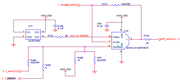
    Is your customers design following the same design as the audio daughter card?  AMUTE pin is generally used to send mute signal to the ADC. but on the audio DC, we noticed that the AMUTE pin on the audio daughter card is connected to a clock mux as shown below which could have been causing the issue.

    Regards,