This thread has been locked.

If you have a related question, please click the "Ask a related question" button in the top right corner. The newly created question will be automatically linked to this question.

TMS320C6747: Known Problems With Using external Crystal Circuitry

Part Number: TMS320C6747

Hello,

We have been using a 24 MHZ external crystal in conjunction with the internal oscillator for the TM320C6747, 

We have noticed that in various instances, a board that fails to start up may work if we replace the TM320C6747 whilst keeping everything the same. Thus, what are some issues that have been reported regarding external crystals specifically using the TM320C6747?

Thank you,

Jair

  • Hi Jair,

    I've forwarded this to the design experts. Their feedback should be posted here.

    BR
    Tsvetolin Shulev
  • Jair,

    Have you checked the Schematic review checklist regarding the clocking requirements:
    processors.wiki.ti.com/.../_AM1x_Schematic_Review_Checklist

    Regards,
    Rahul
  • Rahuk,

    Yes I have. Thank you. Under clocking, our schematic meets the data sheet requirements. 

    With respect to that, what are all the things that could be causing the DSP to not boot up?

    Also, what are the sequence of events that the DSP goes through prior to fetching code from external memory?

    Any other recommendations to what could be the problem? 

    Thank you,

    Jair 

  • I have asked the hardware and system experts to chime in on this issue.

    When you come across a DSP boot failure, can you connect an emulator? If yes, it may be good to capture the system state using the debug GEL file that we provide here to see if the bootloader is providing any error codes that can indicate any issue.
    processors.wiki.ti.com/.../OMAP-L1x_Debug_Gel_Files

    Have you captured any scope shots of SYSCLK output or boot media data pins to see if the ROM bootloader is even starting on the failing parts. Also, indicate the silicon revision for these devices that you are using to see if any errata issue is impacting your design.

    Regards,
    Rahul
  • Hi Jair, I was wondering what's leading you down the path of the crystal / oscillator being the issue. If you're looking in that direction, have a look at section 6.5 of the C6747 datasheet. It's got some specs as to the crystal's ESR, the value for the load capacitors, etc.

    Just for background: by far the majority of products that I've seen using this device (I'm talking millions of units) use the 24 MHz crystal + internal oscillator. It's a really well-proven implementation. If you get the circuit wrong, sometimes you can encounter a situation where the oscillator doesn't start up. One thing that you can do is probe at the crystal itself during a boot failure and see if you can see oscillation or not. If the clock just isn't there, obviously you won't boot.

    In general, if you pick the right components, put the crystal near the DSP, etc, you shouldn't have any issue there.
  • Hello Tufino and Rahul,

    Thank you both for the thorough responses. I'll try to re-account the experiences that we have been having.

    Our initial assumption was that it was the crystal. But we went through 8 DSP's where we weren't getting the DSP to start up, and we were receiving the correct waveform from each crystal.

    The catch here is that we aren't sure if the waveform was already there before checking with the oscilloscope, as the probe from the oscilloscope could add capacitance. Nonetheless, the waveform at 24 MHz and ~1.2 Volts is there when measuring the crystal.

    Using a 24 MHz crystal with a load value of 18 pf, and the correct capacitors of 36 pf (all of these meeting the specs listed in section 6.5), the board will not boot up.

    Even more, if we probe the crystal at boot up, we have had had instances of the board booting up. And once the board boots up, once we reset it without probing the crystal, it boots up again and again as we press reset.

    In contrast, if we aren’t probing the crystal at boot up, but probe it later, the DSP does not start up, but as mentioned before, the crystal is outputting the correct signal.

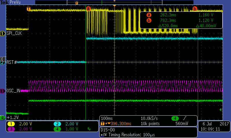
    One occurrence we have seen is that after we probe the crystal, we see the clock from the flash try to retrieve code about every ~ 13 seconds. Is this something that the DSP is designed to do?

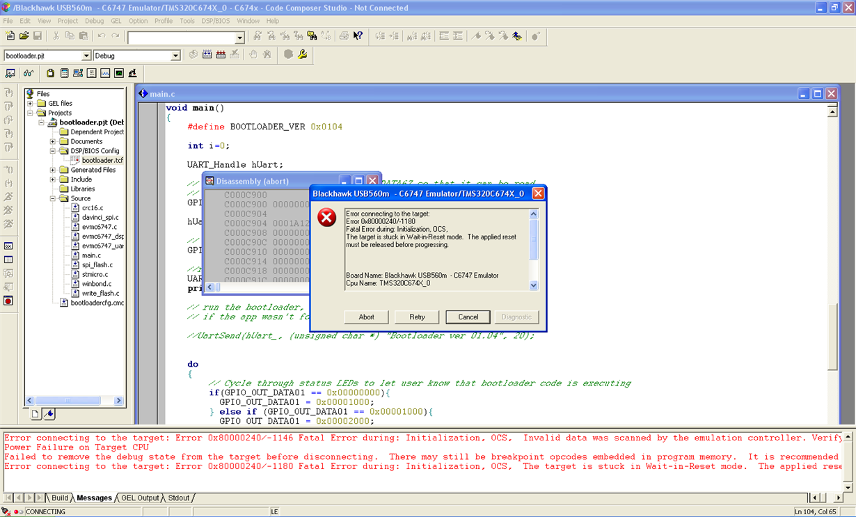
    On the boards that are not able to boot up, we cannot connect the emulator. Is there another way to connect the emulator to these boards? (Screenshot attached of the error we are getting)

    To eliminate the firmware as the possible cause of this issue, we loaded the basic bootloader onto a working DSP. However, we could not access the firmware from the bad boards via the emulator. To change the firmware, we removed the flash from another board that we were able to connect to; we loaded bootloader code onto the flash from a good board and switched that with a flash from the bad board. Simply, this allowed us to eliminate the variable that the firmware from the DSP was causing the problem as the board still did not boot.

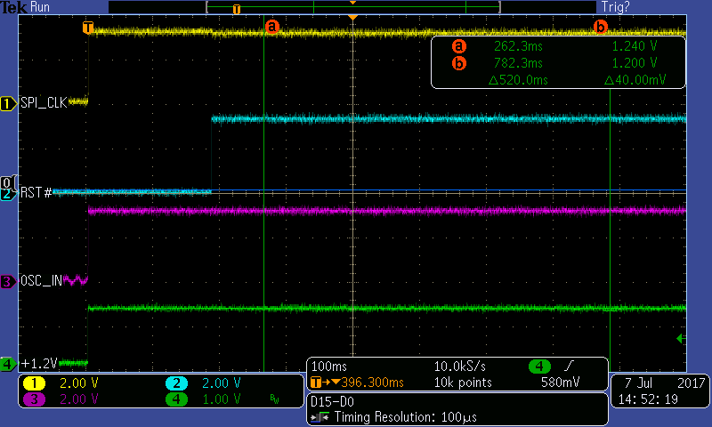
    Attached is a screenshot of the scope shots of system clock, reset, oscillator out (ignore that it says “IN”) and our 1.2V power source. One screenshot, “badboard.png” shows the board that isn’t booting up with “oscillator out” (EMA_CLK/OBSCLK/AHCLKR//GP1) not coming up at all, yet the crystal has an output. The other goodboard.png shows our system operating as it should with a board that started up correctly.

    Lastly, I can't say that every board that doesn't start up is Revision D, and I do have some that are Revision D that work. Nonetheless, every board that doesn't start up that I have on hand is revision D.

    Right now, I am not sure how to diagnose the problem, so your input would be greatly appreciated!

    Thank you very much,

    Jair

  • Hi 

    Based on some of the symptoms I see here, can you also explore the guidance in the following wiki

    This section is included in the OMAPl1x schematic checklist, and but specifically talks about crystals, Rs and Rbias.

    As Bobby mentioned the device has been in production for long time with several million units with 24 MHz crystal based designs, and things just work.

    However we have had some instances where due to design, board or crystal marginalities it is recommended to have provision for Rs in the board and see if that helps. Is this something you can blue wire to explore ( i see that adding a probe also makes the issue go away etc).

    Regards

    Mukul 

  • Hi

    You may also find the following post useful

    6746 is a different device family but the same oscillator circuit

    Regards

    Mukul

  • One question that I have. On some boards, we have gotten the board to boot up by using an external oscillator circuit supplying the 1.2V oscillation . On page 69 of the DSP documentation , it mentions that the CLKMODE bit in the PLLCTL register must be 0 to use the on chip oscillator. If CLKMODE is set to 1, the internal oscillator is disabled.

    Does that bit absolutely need to be changed? If so, why does it need to be changed if it always defaults to the internal oscillator at power up nonetheless?

    If the internal oscillator was still enabled, what problems, if any, would we experienced from creating an external circuit with an oscillator?

    Quite simply, if possible, it would be favorable for us to be able to change the circuitry to using an external oscillator while keeping the firmware (that previous bit), the same.
  • Hi Jair
    Please see the following old post
    e2e.ti.com/.../105824
    Hope this clarifies the CLKMODE configuration.
    Let me know if you have any question.

    So it appears that you are planning to use an external oscillator to get around the issue?
    Additional recommendation when using an external oscillator , is to look at usage note 2.1.3 in the silicon errata. If your products require testing for ESD strikes etc as IEC 61000-4-2. ,it may be anyways good to use an external osc

    Regards
    Mukul
  • Sorry the usage note number is 2.1.5 (not 2.1.3)