This thread has been locked.

If you have a related question, please click the "Ask a related question" button in the top right corner. The newly created question will be automatically linked to this question.

RTOS/TMS320C6748: SPI In Slave Mode, SPI tx interrupt continuously triggered

Part Number: TMS320C6748

Tool/software: TI-RTOS

Hi,

I am using the following platform  Tm320C6748 running DSP BIOS 5, (Custom Board) and PSP drivers 01_30_01

I configured the SPI in slave mode, operation mode is interrupt mode.

seems that SPI tx interrupt continuously triggered even before I write anything to the transmit buffer.

Once SPI is ebabled tx interrupt is triggered.

any suggestions  why the tx interrupt triggers ? 

Alex Levit.

  • Alex,

    It would be good to use the latest software for a new product development, which would be the Processor SDK with TI-RTOS. The functionality of TI-RTOS is virtually the same (tasks, software interrupts, hardware interrupts, periodic interrupts) as with DSP/BIOS but the API names are slightly different and the construction of the OS is a little different. If you cannot do that, just be aware that support from here may be a little less strong for the older software.

    Please explain what you are observing when you say the SPI Tx interrupt is "continuously triggered".

    There are several registers in the SPI register set that indicate the cause of an interrupt. What are those bit settings?

    How are you responding to the interrupts in your ISR? If the interrupt is requesting data to be transmitted (not an error interrupt), are you sending data? Are you handling and clearing the interrupt as described in the documentation?

    Are you following an example from the software libraries or CSL?

    Why are you not using the DMA to handle the data transfers? That is much more DSP-efficient than using an ISR for data transfers.

    Regards,
    RandyP
  • Hi Randy,


    The SPIFLG register Value  after enabling SPI (writing 1 to SPICFG.ENABLE)   is 0x01000200 (No errors) only TX empty interrupt is set.

    I do not attempt to transmit at this stage, i do call GIO_Read which is soposed to pend on SEM till Master will transmit any data (DSP is SLAVE).

    the program is running at Spi.c -> spiIntrHandler() routine (pspdrivers_01_30_01).

    see following code sample for the Spi.c file 

    while ((0 != intStatus) &&
    (NULL != chanHandle) &&
    (Spi_OpMode_INTERRUPT == instHandle->opMode))

    {

    .

    .

    .

    /* Transmit data Handling is done here */
    if (CSL_SPI_SPIFLG_TXINTFLG_MASK
    == (intStatus & CSL_SPI_SPIFLG_TXINTFLG_MASK))
    {
    if (0 != chanHandle->txBufferLen)

    // do somthing

    }

    }

    the chanHandle->txBufferLen is 0 in my case, i do not send ant data at this stage.

    this causes my system to stack because GIO Read is not pending.


    I do not follow example from the software libraries or CSL they do not have DSP SPI in slave mode example.

    i agree DMA is more efficient but i don't believe this will resolve my issue.

    Alex.

  • Hi Alex,

    The SPI Loopback example provided in Processor SDK can be easily modified to work in slave mode. I've gone ahead and modified it and attached it below for your reference. Just replace the main.c file in the example project with this file. 

    main_spi_slave_example.c

    I recommend using this as there are no planned bug fixes or updates to the software package you are using.

  • Hi Sahin Okur,

             I use the main_spi_slave_example.c you provided.

             In my case, the C6748 communicate with ESP32  (a wifi/ble module). The ESP32 works as SPI master and the C6748 works as SPI slave. The master SPI_CLK is 1MHz. And both set as data changes in the falling edge and data sample at rising edge.

             And for test, I make the MASTER send 16bytes every second.

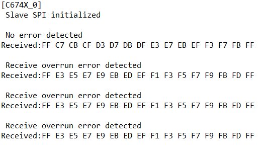
             I tried the main_spi_slave_example.c , but the result is

            The ESP32 send 0xFF,0xF1,0xF2,0xF3,0xF4,0xF5,0xF6,0xF7,0xF8,0xF9,0xFA,0xFB,0xFC,0xFD,0xFE,0xFF

            But the DSP got:


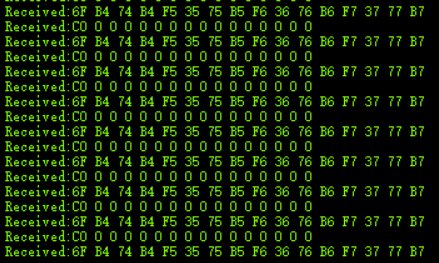
               And the DSP send out: 0xDF,0xD1,0xD2,0xD3,0xD4,0xD5,0xD6,0xD7,0xD8,0xD9,0xDA,0xDB,0xDC,0xDD,0xDE,0xDF;

            But the ESP32 got:

                      I'm sure the ESP32 works normally, because:

               1. I monitor the SPI wires with oscilloscope, the waveform is right, the MISO sent out by DSP is not right.

               2. I use 2 ESP32 module one as master and one as slave, the SPI communicaton works normally at 20MHz with the same master code.

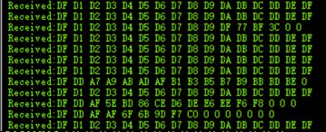
               I've also tried the stareware SPI_DMA exmaple for the C6748 , the example is in master mode and I change it to slave mode, I find the SPI MISO sent out by DSP is not right:

            You can see the laste byte is sometimes 0 and sometimes DF.

             And I monitor the TXDATA in SPIDAT1 register and find that the TXDATA is always "DF", never become "0". So, I think the DMA works normally.

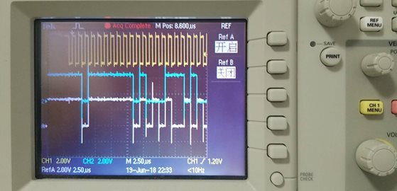
            I monitored the first 2 bytes of MISO with oscilloscope and got:

                 The green is right, the first 2 bytes should be "0xDF D1", while the white is wrong which is "0xDF D5".

           So, I think the SPI module of C6748 works not normally when in SLAVE MODE with the stareware code example.

           My question is , for the main_spi_slave_example.c based on pdk, is any on board experiments have been taken? Thank you.


    Frank