Hi,
We have one DSP(TMS320C6727) on our board. I am trying to run PLL example in PLL mode but DSP is getting hanged on this line
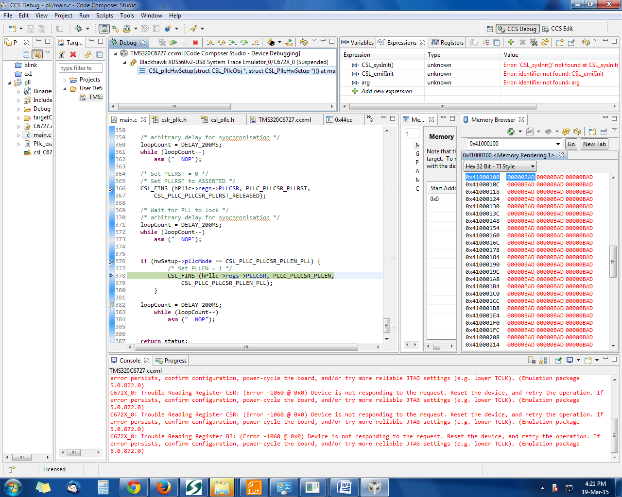
if (hwSetup->pllcMode == CSL_PLLC_PLLCSR_PLLEN_PLL) {
/* Set PLLEN = 1 */
CSL_FINS (hPllc->regs->PLLCSR, PLLC_PLLCSR_PLLEN,
CSL_PLLC_PLLCSR_PLLEN_PLL);
}
The attached code is running fine on evaluation board.
Please provide me suggestions on this problem.