This thread has been locked.

If you have a related question, please click the "Ask a related question" button in the top right corner. The newly created question will be automatically linked to this question.

TMDSLCDK138: audio output noise?

Part Number: TMDSLCDK138

Hi,

We are taking an input signal and looping it back to the output.

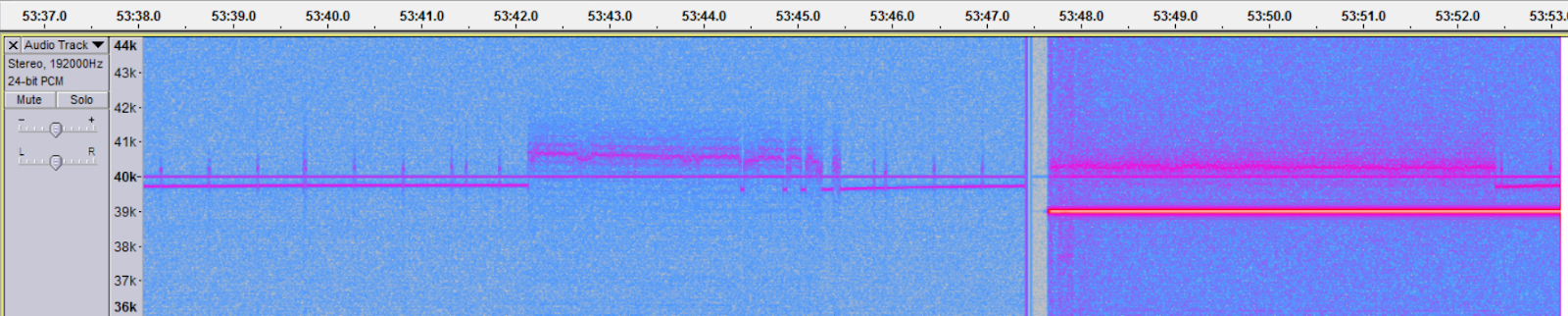
However, we get a pretty strong noise at the output. Any ideas?

  • Hi,

    Can you elaborate a little bit?

    We are taking an input signal and looping it back to the output.

    You mean you take the audio signal from line in (or Mic) of the OMAP-L128 LCDK and use a loopback application to play it (line out)?

    Which software are you using:
    MCSDK Linux or MCSDK RTOS?

    Best Regards,
    Yordan
  • Exactly. We took the Mcasp audio loopback example. 

    It uses EDMA, AIC31, Mcasp, RTOS and cache. 

    That noise is pretty strong, don't you think?

    On the LCDK, we connect the input signal to the upper 3.5mm TRS socket, and the output to the lower. What is the maximum voltage the upper socket (the input) can accept?

  • Nadav,

    Can you try running an audio playback example and see if there is noise on the audio output ?

    Please refer the audio codec datasheet to know the voltage limits.

    www.ti.com/.../tlv320aic3106.pdf

    Regards,
    Senthil
  • Hi Senthil,

    That's exactly what we did. We ran the loopback example.
    Please run the example on your side, and post here the output like we did, so we can compare the differences in the noise.
  • Nadav,

    The LCDK has an RC filter on the output of the TLV320AIC3106IRGZ codec. It has been too long out of school for me to calculate the cutoff frequency from the 10K/10uF RC pair, but I am sure it was designed to cutoff the output well under 20KHz.

    Your noise shown on the output is at additive noise that is clearly on the order of 20KHz and should not be able to get through that filter.

    Please do the following:

    1. Place the second scope probe on the codec side of the filter capacitor. How does the noise vary from what you have shown?
    2. Modify the loopback code to capture a circular buffer of the last 100 output samples. Look at those values and see if they appear to be rising and falling as you would expect for a sine wave without the noise.
    3. Generate a sine wave and output that value, ignoring the input signal. How does that generated output appear on either side of the filter capacitor?

    Many of our examples use a sampling frequency of 8KHz. What sample rate have you configured your codec for?

    The sample rate required to generate the noise you show is quite high. Although the codec can work up to 96KHz, few of our examples run that high.

    Your observations and replies will be helpful.

    Regards,
    RandyP
  • Hi,

    This what happens (the spectrum) when I load a program that generates a constant 39khz wave (ignores the input). The DSP card works on a 96000khz sampling rate:

    As you can see, after we load the code, the background becomes darker (blue). That means that there is more noise at the output. Furthermore, before we even load the code, when the background is light blue, there's still too much noise. The only time when there is no background noise is the tiny bright gap that you see in the middle, when the code is loaded. That's the same good noise level that occur when the DSP card is not connected to the sampler (audacity) at all, and that's what we want it be... The noise level is very (very) important to our application, and we can't live with so much noise in the background. We need a clean signal...

  • Nadav,

    As Senthil said, please run one of our examples. I do not believe our examples operate at 96ksps.

    Since you have noise when the DSP is not running, nothing we do with the DSP will remove that. You have problems other than the DSP code. Since the axes are not labeled, I do not know what the picture shows.

    Please follow and respond to my previous suggestions for debug.

    Since you have a typo in the sampling rate (not capable of 96MHz sampling rate), do you have a typo in the 39kHz value? I assume that is not a typo based on the solid line at 40k on the picture. That is much too high, so please reduce it to 1kHz for debug.

    Regards,
    RandyP