Hi,
My customer is a bit confused by uPP clock polarity. I believe the polarity can be controlled via uPP Interface Configuration Register (UPICR). Let`s assume they are using channel A for receiving data from external device (FPGA or something).
Now TRM says like this:
CLKINVA Channel A clock inversion. Controls clock signal polarity for interface Channel A.
0 Clock is not inverted. Channel A signals align on rising edge of clock.
1 Clock is inverted. Channel A signals align on falling edge of clock.
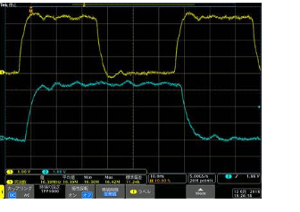
I need to clarify the meaning of "align". In this case, I regarded "align" as "latch". My understanding is, using 0 to latch the control and data signals with rising edge, and using 1 to latch the control and data signals with falling edge. So we should configure CLKINVA bitf-ield as 1 if the actual waveform looked like this:
Yellow : Clock
Blue : In coming signals (START, ENABLE or DATA lines), where the polarity of control signals have been configured as active high)
Is my understanding correct ?
Best Regards,
NK


