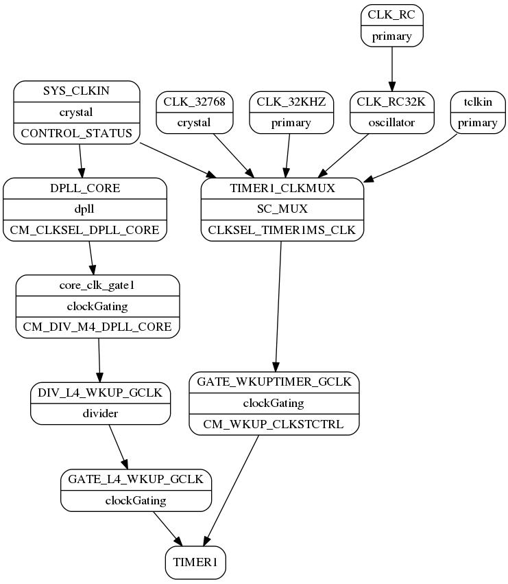
While tracking down a bug with one of my timers I grew tired of bouncing around the SPRUH and data sheet trying to figure out what clocks were feeding my timer. I played with the clock tree tool but had trouble with my Java interpreter not updating the display properly. So, in a fit of Python programming, I parsed the XML file for the clock tree tool model and generated graphs for each of the modules.
Here's the graph for TIMER1:
For each node, the top line is the name of the node. The second line shows the type of node. The third line, if present, gives the controlling register. You should note that this is the internal representation of the clock tree tool and may not be a perfect model of the device. There are some oddities in the model. For instance, it shows the UART5 divider in the clock chain of I2C0. Still, it's been helpful to me in finding my problem.
The full documentation is in a biggish PDF file. I don't think there's any way to post it here. I hesitate to put it on a public web site since it seems to be a gray area in the clock tree tool's license agreement regarding disassembling the source code. I would appreciate any input from TI on that subject.
For now I'll share with anyone interested via email.
James


