This thread has been locked.

If you have a related question, please click the "Ask a related question" button in the top right corner. The newly created question will be automatically linked to this question.

Difficulty with TI-RTOS Lab 5 for OMAPL138 LCDK

Other Parts Discussed in Thread: OMAPL138, OMAP-L138

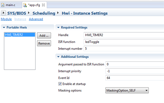
I have been working through the Kernal Workshop for the TI-RTOS to get up to speed on working with the OMAP L-138 processor.  In lab 5 I am supposed to initiat a LED to blink based on a HWI on timer 0 3/4.  The first thing I noticed is that the lab calls for there to be a InitCpuTimers() function call.  I do not see this in the C6000 main.c file but I do see a lot of code that would be setting up the timers in the hardware_init() function.  I am not sure if the file I have is missing something or not.  I have been setting up the HWI interrupt as such:

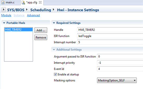
When I use this configuration I get no output on the LED.  The interesting thing is that if I change the event ID to 4 (Timer0 1/2) system tick I then get a nice 500hz square wave signal.   

As a result it seems like the HWI is setup mostly correctly but there is just something missing.  I don't know if the timer is just not fully configured or if I am missing something more fundamental here.  Any advice would help here.  

Config

TI-RTOS for C6000 2.0.1.23

UIA: 2.0.0.28

CCS:  6.0.0.00190 

HW:  OMAPL138 LCDK

JTAG:  XDS100v2 USB Emulator

  • Hi Koplan,

    I am not familiar with the lab example you are working on but from your problem description, it looks like you need to create a Timer instance and not a Hwi instance.

    Here's what you need to do. Open the cfg file in CCS and from the UI select the Timer module. In the Timer module, you will see a link to a device-specific Timer support module. Select that link. It will open a Timer64 page. You can add this Timer64 module to your configuration and use it to create a timer instance for Timer 0 3/4.

    When you create a timer instance, you will also specify a Timer ISR function which will be called each time the timer expires. You can toggle the LED in this function. The timer module manages timer init code as well as setting up a Hwi for you.

    Best,

    Ashish

  • Ashish,

        Thank you for your reply.  The labs/online class that I am speaking of is on the TI website but can be found at:

    http://processors.wiki.ti.com/index.php/TI-RTOS_Workshop#Intro_to_TI-RTOS_Kernel_Workshop_Online_Video_Tutorials

        Actually, the follow on portion of this lab is to do exactly what you said, using the Timer module instead of the HWI in order to blink the LED.  With that said, the I feel like if I can't get this working with the HWI as the lab and instructions state that I am missing something fundamental about how to work with the HWI which will be key to any future designs.  As a result, although I can move forward and try this with the timer module I feel I first really need to get this going with the HWI first.  

  • HI, this is Eric Wilbur - the author of the TI-RTOS workshop. I hope I can help.

    First, the first part of this lab is designed to simply add an Hwi that responds to an interrupt. The easy interrupt to set up is the timer - so we do this via LogicPD's BSL calls in the function hardware_init() here:

    //-----------------------------------------------------------------------------
    // hardware_init()
    //-----------------------------------------------------------------------------
    void hardware_init(void) //called by main
    {
    I2C_init(I2C0, I2C_CLK_400K); // init I2C channel - BSL
    LED_init(); // init LED BSL

    // Timer_0 3:4 setup code using BSL

    TMR0->GPINT_GPEN = GPENO12 | GPENI12; // enable muxed pins as GPIO outputs and
    TMR0->GPDATA_GPDIR = GPDIRO12 | GPDIRI12; // disable all related interrupts

    TMR0->TGCR = 0x00000000; // stop and reset timer 0
    TMR0->TCR = 0x00000000;

    // config timer0 in 32-bit unchained mode, remove timer0 (3:4) from reset
    SETBIT(TMR0->TGCR, PRESCALER(1) | TIMMODE_32BIT_UNCHAINED | TIM34RS );

    // config timer 0 3:4 timer and period registers 0x
    TMR0->TIM34 = 0x00000000;
    TMR0->PRD34 = 0x500000;

    SETBIT(TMR0->TCR, ENAMODE34_CONT); // start timer0 3:4, continuous mode

    }

    As you can see, this sets up Timer0:34 in 32-bit unchained mode, sets the GPIO pin for the LED as an output and the timer period for 500ms delay to blink the LED. This creates a timer interrupt on Event Id #64.

    Your reference to the function InitCpuTimers() was simply a screen capture in the lab (step 9) that was for the C28x. This class supports four architectures, so I always screen cap ONE of the four and say "yours will look similar". The code above that I copied from the solution is your timer setup code.

    My suggestion is that you import the solution for Lab5 (first part) and build and run it. If it works fine, then your lab code IS missing something. You can do a diff on the main.c files that will probably instantly show the problem - that's what I do in class to help solve problems that are not obvious to me.

    Yes, part two of the lab shows how to use the Timer module in BIOS, but I don't carry that code fwd in the next lab because I want to generate an interrupt (like GPIO, or I2C or external - I happen to pick the timer interrupt) to model a system interrupt being processed and handled by BIOS via an Hwi.

    Also note that the LogicPD BSL code (under the hood) uses timer 0 and timer 1 for internal timing. This is NOT BIOS compliant at all - in fact, their code steps on BIOS and vice versa. Note the comment at the top of main.c here:

    //-----------------------------------------------------------------------------
    // Project: Blink LED on C6748 EVM Using Hwi (SOLUTION)
    //
    // Author: Eric Wilbur (Aug 2013)
    //
    // Note: the USTIMER_init routine from Logic PD's BSL initializes two timers -
    // Timer 0 and Timer 1. We overwrite the Timer0(3:4) values for the
    // timer used in this lab. USTIMER_init() should NOT be used in BIOS
    // programs because it conflicts with BIOS timers for Clock and
    // Timestamp. However, the I2C_init() routine calls USTIMER_delay()
    // which needs USTIMER_init(). Oh boy. Solution? The author wrote a
    // BIOS compatible USTIMER_delay() fxn (at the bottom) that is used by
    // the BSL calls internally. And all is well...
    //-----------------------------------------------------------------------------

    I had to write a function that is used by the LogicPD BSL in order to make it BIOS compliant. For C6000, Timer 0:12 is used for the Clock module which is set up implicitly by BIOS. This is why I used Timer0:34.

    I verified the solution works fine in my environment and many students have run this lab successfully. So I hope that the diff on your main.c vs. the solution's main.c will point to the error. If not, let me know and I will investigate further...

  • Wait a second. I think I missed a BIG part of your initial post. You are using the OMAP-L138 LCDK. I assumed you were using the LogicPD OMAP-L138 EK with the older lab set for that board using the LogicPD BSL. In June, I released a new version of the workshop (2.0) that runs on the C6748 LCDK. This is a whole new code set because it is based on the MCSDK (multi-core s/w dev kit) - completely different (and way better) than the old LogicPD BSL.

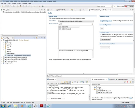
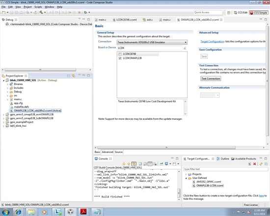
    You cannot mix those two code sets because they are board dependent. So if you are using the OMAP-L138 LCDK, you need to use the latest code set. The only change is that you need a different target config file (that sets up both CPUs) and you need to connect to the ARM first, then the C6748 (different gel file) and then load the project onto the C6748 CPU only.

    The newer hardware_init() function that uses the MCDSK (CSL) looks like this:

    //-----------------------------------------------------------------------------
    // hardware_init()
    //-----------------------------------------------------------------------------
    void hardware_init(void) //called by main
    {

    // PINMUX SETUP ---------------------------------------------

    // Key to be written to enable the pin mux registers for write
    sysRegs->KICK0R = 0x83e70b13;
    sysRegs->KICK1R = 0x95A4F1E0;

    // Enable the pinmux for the GPIO bank 0 pin 9 (tied to LED on LCDK)
    sysRegs->PINMUX0 = ((CSL_SYSCFG_PINMUX0_PINMUX0_27_24_GPIO0_9)
    << (CSL_SYSCFG_PINMUX0_PINMUX0_27_24_SHIFT));

    // mux between Timer 0/1 and GPIO[8:11], enable Timer0/1
    sysRegs->PINMUX4 = CSL_FMKT(SYSCFG_PINMUX4_PINMUX4_3_0,TM64P0_OUT12);


    // GPIO SETUP ---------------------------------------------

    // First, enable the GPIO Module in the PSC
    gpioPowerOn();

    // Configure GPIO0_9 (GPIO0_9_PIN) as an output
    CSL_FINS(gpioRegs->BANK[0].DIR,GPIO_DIR_DIR9,0);


    // TIMER_1 3:4 SETUP --------------------------------------

    // Select 32 bit unchained mode, take Timer0 out of reset
    // Set prescalar value for Timer0 3:4 to 0x1
    // Note: TTIM12RS must be set to NO_RESET also for code
    // to work properly even though Timer0 3:4 is being used

    tmr0Regs->TGCR = CSL_FMKT(TMR_TGCR_TIMMODE,32BIT_UNCHAIN)
    | CSL_FMKT(TMR_TGCR_TIM12RS,NO_RESET)
    | CSL_FMKT(TMR_TGCR_TIM34RS,NO_RESET)
    | CSL_FMK(TMR_TGCR_PSC34,0x1);

    // Set timer0 PRD3:4 to ~ 1/2 second
    CSL_FINS(tmr0Regs->PRD34,TMR_PRD34_PRD34,0x7A0000);

    // Enable/Start TIMER0 3:4 - continuous mode
    CSL_FINST(tmr0Regs->TCR,TMR_TCR_ENAMODE34,EN_CONT);

    }

    This does the same thing as the previous LogicPD BSL code - but uses the MCSDK/CSL calls instead. Once again, if you import the SOLUTION for lab5 and compare the main.c files between your lab and the solution, again, you may find the problem.

  • I did a diff on my Main.c and the "Solution" Main.c and found the only differences where in my commented out "delay" function vs. being completely removed.  With that said, I went ahead and removed that completely to bring it exactly in line with the solution file and I got the same result.  Compiles, loads, just doesn't blink. (File attached below).  If I set a break point in ledToggle it is as if it never actually reaches the ISR because it never breaks.  It feels like the timer never starts running.  

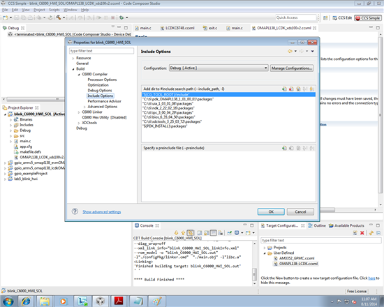
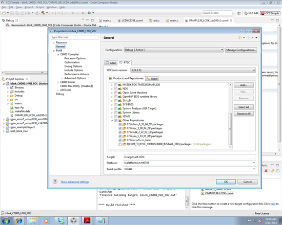
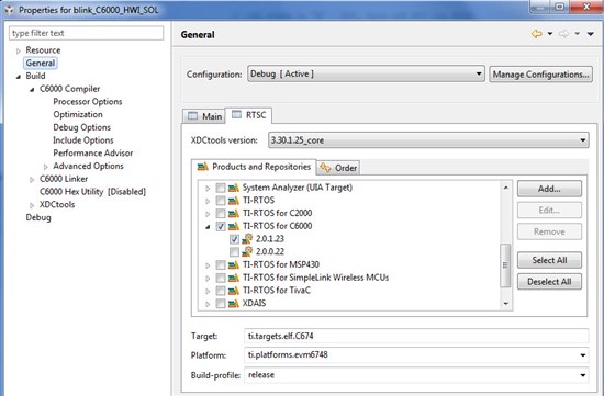
    I then went ahead and attempted to "import" the solution into my workspace.  Doing this I had multiple issues.  The first was that I was getting an error related to the "Can't fine platform package 'ti.platforms.evm6748'. TI platforms no longer shipped....  This was able to be remedied by changing the TI-RTOS for C6000 version to 2.0.1.23 in the project configuration.  Once I remedied this and got the correct include for the PDK into the project it compiled and ran fine but I still did not get the LED to blink. 

    To help verify that my HW is not broken I went onto the "Timer" portion of the lab and that worked perfectly without any problem and was very straightforward.  


    2148.7455.main.c
    //-----------------------------------------------------------------------------
    // Project: Blink LED on C6748 LCDK Using Hwi (STARTER)
    // Author:  Eric Wilbur
    // Date:    June 2014
    //
    // Follow these steps to create this project in CCSv6.0:
    // 1. Project -> New CCS Project
    // 2. Select Template:
    //    - TI-RTOS for C6000 -> Kernel Examples -> TI Target Ex -> Minimal ->
    //    - this template does NOT contain UIA/RTOS Analyzer support
    // 3. Add UIA from available products
    // 4. Add main.c from TI-RTOS Workshop Solution file for this lab
    // 5. Edit as needed (to add/subtract) BIOS services, delete given Task
    // 6. Add include search path for PDK
    // 7. Build, load, run...
    //-----------------------------------------------------------------------------


    //-------------------------------------------------------
    // BIOS header files
    //-------------------------------------------------------
    #include <xdc/std.h>  						//mandatory - have to include first, for BIOS types
    #include <ti/sysbios/BIOS.h> 				//mandatory - if you call APIs like BIOS_start()
    #include <xdc/runtime/Log.h>				//needed for any Log_info() call
    #include <xdc/cfg/global.h> 				//header file for statically defined objects/handles
    #include <xdc/runtime/Timestamp.h> 			//when using Timestamp APIs (TSCL/H), 32bit, 64bit
    
    
    //-------------------------------------------------------
    // MCSDK-PDK-CSLR Include Files
    //
    // Note: to use these header files, please add the
    // following path to your Include Search Path:
    // "C:\TI\pdk_OMAPL138_1_01_00_02\packages"
    //
    // Or similar - based on your actual install
    //-------------------------------------------------------
    #include <stdio.h>
    #include <c6x.h>
    #include <ti/csl/soc_C6748.h>
    #include <ti/csl/cslr_gpio.h>
    #include <ti/csl/cslr_syscfg0_C6748.h>
    #include <ti/csl/cslr_psc_C6748.h>
    #include <ti/csl/cslr_tmr.h>
    
    
    //-------------------------------------------------------
    // PROTOTYPES
    //-------------------------------------------------------
    void hardware_init(void);
    void ledToggle (void);
    void gpioPowerOn(void);
    
    
    //-------------------------------------------------------
    // Globals
    //-------------------------------------------------------
    volatile int16_t i16ToggleCount = 0;			// keep track of # LED toggles
    
    // sys config registers overlay
    CSL_SyscfgRegsOvly   sysRegs  = (CSL_SyscfgRegsOvly)(CSL_SYSCFG_0_REGS);
    // Psc register overlay
    CSL_PscRegsOvly      psc1Regs = (CSL_PscRegsOvly)(CSL_PSC_1_REGS);
    // Gpio register overlay
    CSL_GpioRegsOvly     gpioRegs = (CSL_GpioRegsOvly)(CSL_GPIO_0_REGS);
    // Timer register overlay
    CSL_TmrRegsOvly tmr0Regs = (CSL_TmrRegsOvly)CSL_TMR_0_REGS;


    //---------------------------------------------------------------------------
    // main()
    //---------------------------------------------------------------------------
    void main(void)
    {
    
       hardware_init();							// init hardware via Xware
    
       BIOS_start();							// start BIOS Scheduler (never returns)
    
    }


    //-----------------------------------------------------------------------------
    // hardware_init()
    //-----------------------------------------------------------------------------
    void hardware_init(void)						//called by main
    {
    
    // PINMUX SETUP ---------------------------------------------
    
    // Key to be written to enable the pin mux registers for write
        sysRegs->KICK0R = 0x83e70b13;
        sysRegs->KICK1R = 0x95A4F1E0;
    
    // Enable the pinmux for the GPIO bank 0 pin 9 (tied to LED on LCDK)
        sysRegs->PINMUX0 = ((CSL_SYSCFG_PINMUX0_PINMUX0_27_24_GPIO0_9)
                            << (CSL_SYSCFG_PINMUX0_PINMUX0_27_24_SHIFT));
    
    // mux between Timer 0/1 and GPIO[8:11], enable Timer0/1
        sysRegs->PINMUX4 = CSL_FMKT(SYSCFG_PINMUX4_PINMUX4_3_0,TM64P0_OUT12);
    
    
    // GPIO SETUP ---------------------------------------------
    
    // First, enable the GPIO Module in the PSC
        gpioPowerOn();
    
    // Configure GPIO0_9 (GPIO0_9_PIN) as an output
        CSL_FINS(gpioRegs->BANK[0].DIR,GPIO_DIR_DIR9,0);
    
    
    // TIMER_1 3:4 SETUP --------------------------------------
    
    // Select 32 bit unchained mode, take Timer0 out of reset
    // Set prescalar value for Timer0 3:4 to 0x1
    // Note: TTIM12RS must be set to NO_RESET also for code
    // to work properly even though Timer0 3:4 is being used
    
        tmr0Regs->TGCR = CSL_FMKT(TMR_TGCR_TIMMODE,32BIT_UNCHAIN)
    		                 | CSL_FMKT(TMR_TGCR_TIM12RS,NO_RESET)
                             | CSL_FMKT(TMR_TGCR_TIM34RS,NO_RESET)
                             | CSL_FMK(TMR_TGCR_PSC34,0x1);
    
    // Set timer0 PRD3:4 to ~ 1/2 second
        CSL_FINS(tmr0Regs->PRD34,TMR_PRD34_PRD34,0x7A0000);
    
    // Enable/Start TIMER0 3:4 - continuous mode
        CSL_FINST(tmr0Regs->TCR,TMR_TCR_ENAMODE34,EN_CONT);
    
    }
    
    
    //-----------------------------------------------------------------------------
    // ledToggle() ISR (called by BIOS Hwi, see app.cfg)
    //-----------------------------------------------------------------------------
    void ledToggle(void)							//called by main
    {
    	static Uint32 LED_state = 0;				// used to toggle LED state
    
    	if (LED_state == 1)							// if LED_state is "1" - ON, turn LED ON via GPIO
    	{
    	    CSL_FINS(gpioRegs->BANK[0].OUT_DATA,GPIO_OUT_DATA_OUT9,1);
     	}
    	else										// LED_state is "0" - OFF, turn LED OFF via GPIO
    	{
    		CSL_FINS(gpioRegs->BANK[0].OUT_DATA,GPIO_OUT_DATA_OUT9,0);
    	}
    
    	LED_state ^= 1;								// toggle LED state


    	i16ToggleCount += 1;						// keep track of #toggles
    
    	Log_info1("LED TOGGLED [%u] times", i16ToggleCount);
    
    }


    void gpioPowerOn(void)
    {
        volatile Uint32 pscTimeoutCount = 10240u;
        Uint32 temp = 0;
    
    // power on GPIO module in PSC & enable GPIO module
        psc1Regs->MDCTL[CSL_PSC_GPIO] = ((psc1Regs->MDCTL[CSL_PSC_GPIO]
                                            & 0xFFFFFFE0)
                                         | CSL_PSC_MDSTAT_STATE_ENABLE);
    
    // Kick start the Enable command
        temp = psc1Regs->PTCMD;
        temp = ((temp & CSL_PSC_PTCMD_GO0_MASK)
                | (CSL_PSC_PTCMD_GO0_SET << CSL_PSC_PTCMD_GO0_SHIFT));
    
        psc1Regs->PTCMD |= temp;
    
    // Delay enough time for power state transition to occur (status not checked, this is the defn of HOPE)
        while (((psc1Regs->PTSTAT & (CSL_PSC_PTSTAT_GOSTAT0_IN_TRANSITION)) != 0)
            && (pscTimeoutCount>0))
        {
            pscTimeoutCount--;
        }
    
    }


    2148.7331.myHwiLab05.zip

  • Chris,

    Thanks for the attachments. I was able to import your project into my CCSv6.0, build (zero errors) and run (it blinks). I am using the C6748 LCDK. 

    I am at a loss of what to suggest here. First, your code is "perfect". The quotes are meant to a) give you a warm fuzzy that you did everything correctly in the code and w/the BIOS .cfg file - so you succeeded in the lab; b) to give you a cold fuzzy that something is still wrong.  ;-)

    It is hard to debug this from afar. The only difference between our boards is the ARM9 vs. no ARM9. The other differences are:

    - you have System Analyzer checked (enabled) in your app.cfg file (UNCHECK that) - it is already used as part of the TI-RTOS SDK. I had mistakenly checked that in the solution (which I am now fixing FYI in all projects).

    - you are using XDS100v2 and I am using XDS510USB - shouldn't be a problem

    - I am assuming you are connecting to the ARM first, then 6748 CPU, then loading on the 6748 CPU. I assume yes because the timer (lab 5b) works fine for you

    I am straining my brain for some "what if" scenarios that may lead to the answer. As an instructor and BIOS user, this BUGS me.  ;-)  So here are a few questions/ideas:

    1. Did lab 2 and 4 work ok for you? If so, this takes the entire "environment" out of the picture. It means that you and I are the same in terms of building/running in our own environments using different target config files, different processors, but if lab4 works for you, but not lab5, this narrows the field. If lab4 does NOT work for you, well, then this opens the field a bit regarding the possible error.

    2. Uncheck the system analyzer (right-click -> Properties -> RTSC tab -> System Analyzer (UIA)). I suspect this has NOTHING to do with the problem. Just trying to get closer to "equal". Your project worked fine in my environment even with it checked, so I suspect this will do nothing to solve the problem. Can you tell I grasping for straws here?  ;-)

    3. The fact that the timer lab works fine, but the first part of Lab5 does NOT bothers me. The timer module in BIOS replaces the code used in hardware_init() and allows BIOS to set up the timer for you. Assuming our environments are identical (and lab 2 and lab 4 worked perfectly for you) - and the fact that your project built and ran perfectly on the C6748 LCDK that I just tested, points to a mystery. Can I say that?  I just did. I have no idea what the problem could be.

    4. Wait - I just realized I HAVE an OMAP-L138 LCDK...let me run it on that... It didn't work. So, I have been able to verify your problem on the same board. Initially, I was using the OMAP-L138 board to do my initial development work before I chose to use the C6748 LCDK instead. SO, there is something we are NOT doing to get this to work. Duh. I have emailed a few experts to help out.

    5. FYI - the GIE bit is set properly by BIOS. IER (bit 5) is also enabled via BIOS properly. However, IFR bit (5) is NOT set at all which means, as you said, the timer is not firing - otherwise it would blink.

    I will get back to you when I get this lab to work on my OMAP-L138 LCDK via help from others. Still a mystery - but I hope to figure it out soon...sorry for the delay...but we will BOTH learn something in the process...

  • Hi Chris,

    Do you have anything flashed on the NAND flash on the OMAPL138 LCDK? Can you confirm that you have the boot switches set to NO BOOT mode. If you have uboot flashed on the board and have the board setup to NAND boot, you could run into conflicts so it may be good to set the board to no boot mode and give it a try.

    I think the LEDs are GPIO based on the board so after the PINMUX settings are done on the board, you can go to register view and locate the GPIO register and try to manually chnage the GPIO bit to 1 and 0 to vaildate that the LEDs can be toggled manually.

    Regards,

    Rahul


  • Eric,

      Glad to hear you were able to reproduce the same problem with the L138 LCDK.  I went ahead and tried some of your other suggestions without any change.  Let me know what you find out in your investigations.  

    Rahul,

      How do I set the boot dip switches to "no boot".  I don't see that boot mode documented.  I went ahead and set all the switches to off and had no change in my output.  I then did as you suggested and manually set the GPIO pin in the register view.  This indeed would toggle the LED.  

  • Chris,

    On the LCDKs, for SW1, the first four determine the boot mode (switches 1-4). Switches 5-8 are user switches. According to the wiki sites I found, if you have switch 1 (off) and switches 2-4 ON, that is NAND16 boot mode. So whatever is in the flash will boot. However, when CCS is connected to my C6748 LCDK, I have the switches exactly like this, but there is no ARM on that device, so maybe that is why it works fine on the C6748 and not on the OMAP-L138 LCDK. My switches on the OMAP-L board are the same also - 1-off, 2-on, 3-on, 4-on. Maybe this is the problem as Rahul pointed out.

    FYI - my timer lab solution (part b of lab 5) does NOT work on my OMAP-L138 LCDK. You said yours did? That surprises me. So that is a difference in our results.

    I am still looking for "no boot" setting, but I suspect that 0-off, and 1 thru 3 on will still work fine when connected to CCS and loading a program to the C6748 DSP. I know it doesn't, but what I am saying is that I don't think this is the problem. I could be wrong. I tried switches 0-4 all OFF, didn't work. I cannot for the life of me find a reference for "no boot" settings or "emulation only" settings on any wiki pages. 

    If your TIMER lab solution works with your current settings just fine, then the switches are NOT the problem. The only difference between lab 5 (part a and part b) is that BIOS is setting up the timer vs. using CSL/MCSDK calls.

    Rahul - is there something else we should try? Is there a document that clearly explains the SW1 settings for "no boot" ?

    Thanks,

  • At the beginning of this thread, Ashish had mentioned to make use of the timer module with the procedure.  "In the Timer module, you will see a link to a device-specific Timer support module".  As a result I did this instead of strictly following the procedure in the lab.  This could possibly be the difference between our two 5b labs.  Attached is my archive of the working timer project.  7418.myHwiLab05b.zip


  • Chris,

    I was able to run your lab on my board and it works fine. The diffs are:

    - You use the device-specific timer and I use the portable timer (generic) 

    - you used timer 3 (which I didn't know existed) and I used timer 2 (maybe timer 3 is the GP timer/watchdog) and my brain always told me there were three - thinking of the std 64-bit timers 0,1,2

    - BIOS uses Timer 0 for the clock module, so either timer 1 or timer 2 is available (or 3 I guess)

    SO, this means that the SWITCHES and process to run the code is NOT the problem. No boot switch issues and no uboot issues.

    This is back to the difference between how the timer code in hardware_init() via the CSL calls works vs. the device-specific timer code that BIOS uses. This means that none of the future labs (6+) will work for you either since I don't carry fwd the timer module in the rest of the labs - although you could always substitute that.

    Also, there is a difference between the portable timer code (that I use) vs. the device-specific timer code that Chris uses as it relates to the OMAP-L138 LCDK - since this is NOT a problem on the C6748 LCDK.

    Rahul - have you tried Chris' zip files (the original lab 5 he attached way above) on your OMAP-L138 LCDK? Is there something in the hardware_init() code that makes this lab NOT work on this board when it works fine on the C6748 LCDK? This is still a mystery to me and it would be nice to figure this out for future customers who want to use these labs on the OMAP-L138 version of the LCDK.

  • Hi Chris,

    I'm able to run blink your gpio example code.
    I have tried to import your gpio CCS project and I'm not able to succeed.

    So, I have tried in different method,

    1) I have imported the OMAPL138 PDK GPIO example project from MCSDK1_01_00_01 release.
    ti/pdk_OMAPL138_1_01_00_01/packages/ti/csl/omapl138-lcdk/examples/gpio/src

    2) I have copied the content of your code to PDK GPIO example project's file.
     "main.c" into "Gpio_example.c" and "app.cfg" into "gpioExample.cfg"

    3) I have selected the "Exclude from build" option for "intvecs.asm" file through CCS properties since "gpioISR". routine is not required.

    4) Rebuild the gpio example project.

    5) I'm able to load and run on C6748LCDK board and gpio got blinking.

    6) I have created new target configuration for OMAPL138LCDK board and wokeup the OMAPL138 through  "Launch selected configuration" option.

    7) Connect ARM core followed by DSP.

    8) Select DSP core and load gpio out file.

    9) Now, I'm able to load and run on OMAPL138LCDK (DSP core) board and gpio got blinking.

    So, could you please try the same steps which I have done and update us.

    Note:

    I have set boot settings to UART boot on OMAPL138/C6748 LCDK boards when I'm working with these examples to avoid confusion with NAND flash execution.

  • Eric,

    I have actually been able to get everything else through lab 8 up and running with a few of my own tweaks using clocks and timers instead of the HWI setup.  This is good but I still really want to know what was missing in the Lab 5a HWI setup that kept it from working in case I run into that problem in the future.  

    Titus, 

    The problem that we really are having is why Timer0 3/4 is not firing at 500ms intervals.  I can make the LED blink via the GPIO just fine but something is preventing the timer from firing.  Our initialization is setup as:

    //-----------------------------------------------------------------------------
    // hardware_init()
    //-----------------------------------------------------------------------------
    void hardware_init(void) //called by main
    {

    // PINMUX SETUP ---------------------------------------------

    // Key to be written to enable the pin mux registers for write
    sysRegs->KICK0R = 0x83e70b13;
    sysRegs->KICK1R = 0x95A4F1E0;

    // Enable the pinmux for the GPIO bank 0 pin 9 (tied to LED on LCDK)
    sysRegs->PINMUX0 = ((CSL_SYSCFG_PINMUX0_PINMUX0_27_24_GPIO0_9)
    << (CSL_SYSCFG_PINMUX0_PINMUX0_27_24_SHIFT));

    // mux between Timer 0/1 and GPIO[8:11], enable Timer0/1
    sysRegs->PINMUX4 = CSL_FMKT(SYSCFG_PINMUX4_PINMUX4_3_0,TM64P0_OUT12);


    // GPIO SETUP ---------------------------------------------

    // First, enable the GPIO Module in the PSC
    gpioPowerOn();

    // Configure GPIO0_9 (GPIO0_9_PIN) as an output
    CSL_FINS(gpioRegs->BANK[0].DIR,GPIO_DIR_DIR9,0);


    // TIMER_1 3:4 SETUP --------------------------------------

    // Select 32 bit unchained mode, take Timer0 out of reset
    // Set prescalar value for Timer0 3:4 to 0x1
    // Note: TTIM12RS must be set to NO_RESET also for code
    // to work properly even though Timer0 3:4 is being used

    tmr0Regs->TGCR = CSL_FMKT(TMR_TGCR_TIMMODE,32BIT_UNCHAIN)
    | CSL_FMKT(TMR_TGCR_TIM12RS,NO_RESET)
    | CSL_FMKT(TMR_TGCR_TIM34RS,NO_RESET)
    | CSL_FMK(TMR_TGCR_PSC34,0x1);

    // Set timer0 PRD3:4 to ~ 1/2 second
    CSL_FINS(tmr0Regs->PRD34,TMR_PRD34_PRD34,0x7A0000);

    // Enable/Start TIMER0 3:4 - continuous mode
    CSL_FINST(tmr0Regs->TCR,TMR_TCR_ENAMODE34,EN_CONT);

    }

    If you have any insight on this it would be very much appreciated.  

    Thanks,

    Chris

  • Chris,

    I want to know the same thing. From my vantage point, it boils down to:

    - lab5 (Hwi) works on the 6748 LCDK and NOT on the OMAP-L138 LCDK

    - given the fact that using the BIOS Timer module (vs. CSL code that you included above) means that there is no "boot" or ARM issues or boot pin issues.

    - the problem lies between how the BIOS Timer module (device specific) sets up the timer and what is used in the hardware_init() function above. Use the BIOS Timer module, it works. Use the code above, it does NOT work.

    My encouragement to TItus and Rahul is to download the Lab 5 (Hwi) solution from my workshop wiki and import it into CCSv6 and try to make it work on an OMAP-L138 LCDK. I can't find the problem right now and, as Chris said, it bugs me too. Maybe have someone on the BIOS team try it as well - because there is some small difference between what their BIOS Timer module code does that WORKS vs. the MCSDK/CSL code. Weird that it works FINE on the C6748 LCDK, but not the OMAP-L138 LCDK. Mystery.

    Here is the workshop link:

    http://processors.wiki.ti.com/index.php/Introduction_to_the_TI-RTOS_Kernel_Workshop

  • Hi Eric,

    As I emailed you, I'm able to run LAB5 HWI example code on OMAPL138 LCDK board as well C6748 LCDK board.

    If I'm able to see the LED blinking, shall I assume that example code is working fine ?

    or I need to check something else ?

    Hi Chris,

    The problem that we really are having is why Timer0 3/4 is not firing at 500ms intervals.  I can make the LED blink via the GPIO just fine but something is preventing the timer from firing.  Our initialization is setup as:

    1) I have tried to import LAB5 example and got error so I have changed project settings to build (please attached screen shot)

    2) I think, you don't want to connect ARM core followed DSP core instead, you can mention board type as OMAPL138 LCDK in "target configuration" then it connect ARM core followed by DSP then load the binary into DSP core automatically.

  • TItus,

    Thanks for the info. Yes, if it blinks, it is working.

    FYI, this project requires TI-RTOS for C6000:

    I made no mods to the project properties, platform, TI-RTOS, etc. This may be why you were getting errors when you built - you were missing all of the tools in the TI-RTOS SDK.

    I chose the OMAP-L138 LCDK version of the target config file. It blinks fine. I had chosen this target config file before - so I really have no idea why it didn't work before and it works now. I did do a "clean project" before I built this time. That was the only difference. Not sure why that made the difference I saw.

    I cannot simply connect to the DSP without the ARM connected first. If you choose the OMAPL138_LCDK as the target, you get 4 CPUS - DSP, ARM, and two PRUs. If you connect to the DSP only, there is no GEL file that runs and therefore you can't load a program to it. However, if you connect to the ARM first, the gel file runs and wakes up the DSP. Then I connect to the DSP and load the .out file to the DSP. It works fine.

  • Hi Eric,

    Sounds good.

    Thanks for your update.

    Hi Chris,

    Were you able to got working ?

  • I have not gotten a chance to dig into this due to a set of 2 day meetings I am in the middle of.  hope to get back to it Thursday.  

    Thanks,

    Chris

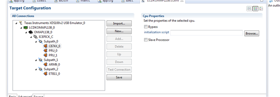
  • I am still not able to get it to blink.  My original configuration was the LCDKOMAPL138.ccxml so I did a build clean and rebuilt and that did not change any of the results.  I even attempted to change it to the c6748 config, load, then change back to the L138 LCDK in order to force updates and flush any changes.  Still no updates.  In the advanced config it looks like:

    Yesterday I even had another one of my engineers working on seeing if he could push through this problem by reading through this forum and following the labs and he spent most of the day trying different configurations with no luck.  Is there any ways that this could be a result of me using the XDS100v2 usb emulator and Eric using a XDS510USB.  At this point his seems like the only difference.  Has anybody gotten this working with a XDS100v2 programmer?


  • Hi Chris,

    Your target configurations seems to be good.

    Have you modified the RTOS LAB example code ?

    I am able to run the RTOS LAB5 HWI example code on OMAPL138 LCDK and C6748 LCDK boards through both XDS100v2 and XDS510USB emulators on CCSv6 and CCSv5 too.

    Just try to set boot switch settings to UART boot (BOOTME) and try.

  • I tried it with the UART bootmode and still didn't help.  I am not sure what I have that is different and thus keeping me from getting this working but at this point I think we are all killing a lot of time for not too much additional gain.  If I move forward with TI-RTOS I would be using it to create timers instead of the manual way in this lab so I think the utility of this exercise is getting low and I have gotten all the other labs to work.  I very much appreciate everyone's support and couldn't have asked for better help from TI and this community.  

    Thanks,

    Chris

  • I am interested in this problem too. There is a warning on the source main.c file:

    The warning is on 32BIT_UNCHAIN. I don't know whether it matters or not.

    I download the project using timer (Blink_target_TIMER), add UIA. The HWI interval is rather quickly than 500 mS.

    There are a lot doc on timer setting for me to read now. Thanks,

  • The above picture was taken by NAND 16 boot mode.

    If it is changed to UART (BOOTME), there is an error with XDS200 emulator:

    This PC (XP) is a little slow. Anyhow, it shouldn't be error. I have lower the clock from 10 M to 1 M, the error is still there. Thanks,

  • Hi Robert,

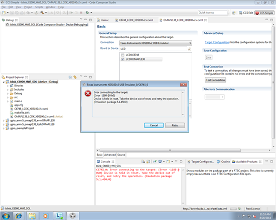
    Device is held in reset

    I also faced this behavior when I run DSP project on OMAPL138 (ARM boot device).

    This issue is different, it is due to DSP is in RESET, for this , you have to run any ARM project on OMAPL138 LCDK (it will load gel file which would wakeup the DSP) board to enable DSP from reset and after that try the DSP project.

  • Hi Titus,


    I have a OMAPL138 LCDK and xds100v2. But I failed to enter the HWI isr.


    Q1: How to set the boot mode to UART boot?

                     SW1   SW2   SW3   SW4   SW5   SW6   SW7   SW8

    value?

    Q2: Could you please share the code and target configuration file on CCSv5 and CCSv6?


    I wonder if I can enter the HWI isr with your target setting and code.

    Thanks!


  • Hi Zhengliang,

    A1) For UART boot :

    1   2   3   4   (SW1)

    0   1   0   1

    http://processors.wiki.ti.com/index.php/OMAPL138_StarterWare_Booting_And_Flashing#How_to_flash_and_boot_the_sample_DSP_starterware_app_on_OMAPL138_LCDK_board

    On OMAPl138 LCDK board,set the boot switches for UART mode(1:4 = 0101 on OMAPL138 LCDK).

    Regarding Q2,

    What problem are you facing ?

  • Hi Titus,


    The problem is that I can't enter the timer Hwi isr. You said your test is good, so I want to run them in my board and see the difference between your code and mine.

    Thanks!

  • Hi Zhengliang,

    Yes, I'm able to run "blink example HWI" on both OMAPL138LCDK and C6748LCDK boards.

    I have attached the both target configurations for XDS100v2 emulator.

    6153.target_config.zip

    Steps that I have followed to run HWI example.

    Emulator : XDS100v2

    CCS version : CCSv6

    1) Set the boot mode to "UART"

    2) Run the HWI example through CCSv6.

    3) If you have faced any error like "Device is held in reset" then try to run any ARM project on the OMAPL138 LCDK board to wakeup the DSP (actually it would call the OMAPL138 LCDK gel file).

    4) Quit the ARM project and run again the same  HWI example on OMAPL138 LCDK board.

    5) Now, you able to see the LED blinking

    6) Try to set breakpoint in "LEDtoggle" ISR routine and able to hit while you running the project for eah LED ON and OFF time.

  • Hi Titus,


    Thank you for your help, I can go into the timer HWI isr now.


    Then I have 2 questions.

    1

    Why use UART boot mode, not Emulation Debug boot mode? Previously I thought that we were using an emulator(xds100v2), we needed to choose emulation debug boot mode.


    2

    OMAPL138 includes C6748, but the code that runs well in C6748LCDK can't run in OMAPL138 LCDK, why?

    Thanks in advance.

  • Hi Zhengliang,

    Why use UART boot mode, not Emulation Debug boot mode? Previously I thought that we were using an emulator(xds100v2), we needed to choose emulation debug boot mode.

    Actually OMAPL138 LCDK board doesn't have emulation support (boot switch) but OMAPL138 SDI and LogicPDEVM does support.

    If you select NAND boot mode then if any executables present in NAND flash then the results could be unexpected. Actually it won't be because the gel file will re-initialize everything.

    So, UART boot mode is not mandatory and any boot method have been used. BUt you will face "target is in reset" error would occur, please refer to the below reply.

    OMAPL138 includes C6748, but the code that runs well in C6748LCDK can't run in OMAPL138 LCDK, why?

    Yes, because the OMAPL138 is ARM+DSP (ARM wakeup first and DSP held in reset)

    You can run ARM app on OMAPL138 board since it is ARM boot device (ARM would wakeup first)

    If you want to run DSP app on OMAPL138 then you need bootloader to wakeup DSP or need to call gel file which is called while you run ARM app.

    You can check the gel file output log when you run ARM app on OMAPL138 LCKD board that you will get "DSB wakeup complete"

  • Chris, Zhengliang,

    Please try changing the Lab 05 code to use Timer 1 instead of Timer 0, and it should work on OMAP-L138 LCDK. The board could be in a boot mode on start up and it may be using Timer 0 as soon it boots on power up. So, configuring the code to use Timer 1 and its interrupt event will work.

    Here are the two changes you need to make on the project:

    1. On app.cfg, use interrupt event id 48 instead of 64

    hwi0Params.eventId = 48;

    2. On main.c file, change the code to use Timer 1 instead of Timer 0.

    CSL_TmrRegsOvly tmr0Regs = (CSL_TmrRegsOvly)CSL_TMR_1_REGS;

    With these changes, the binary should run on both C6748 LCDK and OMAP-L138 LCDK. Also, these are the only changes to be made on Lab 06, Lab 08, Lab 09, Lab 10 to make them work on OMAP-L138 LCDK.

    I am also attaching the modified app.cfg and main.c files that the Lab 05 project uses.

    4111.app.cfg

    2313.main.c
    //-----------------------------------------------------------------------------
    // Project: Blink LED on C6748 LCDK Using Hwi (STARTER)
    // Author:  Eric Wilbur
    // Date:    June 2014
    //
    // Follow these steps to create this project in CCSv6.0:
    // 1. Project -> New CCS Project
    // 2. Select Template:
    //    - TI-RTOS for C6000 -> Kernel Examples -> TI Target Ex -> Minimal ->
    //    - this template does NOT contain UIA/RTOS Analyzer support
    // 3. Add UIA from available products
    // 4. Add main.c from TI-RTOS Workshop Solution file for this lab
    // 5. Edit as needed (to add/subtract) BIOS services, delete given Task
    // 6. Add include search path for PDK
    // 7. Build, load, run...
    //-----------------------------------------------------------------------------


    //-------------------------------------------------------
    // BIOS header files
    //-------------------------------------------------------
    #include <xdc/std.h>  						//mandatory - have to include first, for BIOS types
    #include <ti/sysbios/BIOS.h> 				//mandatory - if you call APIs like BIOS_start()
    #include <xdc/runtime/Log.h>				//needed for any Log_info() call
    #include <xdc/cfg/global.h> 				//header file for statically defined objects/handles
    #include <xdc/runtime/Timestamp.h> 			//when using Timestamp APIs (TSCL/H), 32bit, 64bit
    
    
    //-------------------------------------------------------
    // MCSDK-PDK-CSLR Include Files
    //
    // Note: to use these header files, please add the
    // following path to your Include Search Path:
    // "C:\TI\pdk_OMAPL138_1_01_00_02\packages"
    //
    // Or similar - based on your actual install
    //-------------------------------------------------------
    #include <stdio.h>
    #include <c6x.h>
    #include <ti/csl/soc_C6748.h>
    #include <ti/csl/cslr_gpio.h>
    #include <ti/csl/cslr_syscfg0_C6748.h>
    #include <ti/csl/cslr_psc_C6748.h>
    #include <ti/csl/cslr_tmr.h>
    
    
    //-------------------------------------------------------
    // PROTOTYPES
    //-------------------------------------------------------
    void hardware_init(void);
    void ledToggle (void);
    void gpioPowerOn(void);
    void delay(Uint32 count);
    
    
    //-------------------------------------------------------
    // Globals
    //-------------------------------------------------------
    volatile int16_t i16ToggleCount = 0;			// keep track of # LED toggles
    
    // sys config registers overlay
    CSL_SyscfgRegsOvly   sysRegs  = (CSL_SyscfgRegsOvly)(CSL_SYSCFG_0_REGS);
    // Psc register overlay
    CSL_PscRegsOvly      psc1Regs = (CSL_PscRegsOvly)(CSL_PSC_1_REGS);
    // Gpio register overlay
    CSL_GpioRegsOvly     gpioRegs = (CSL_GpioRegsOvly)(CSL_GPIO_0_REGS);
    // Timer register overlay
    CSL_TmrRegsOvly tmr1Regs = (CSL_TmrRegsOvly)CSL_TMR_1_REGS;


    //---------------------------------------------------------------------------
    // main()
    //---------------------------------------------------------------------------
    void main(void)
    {
    
       hardware_init();							// init hardware via Xware
    
       BIOS_start();							// start BIOS Scheduler (never returns)
    
    }


    //-----------------------------------------------------------------------------
    // hardware_init()
    //-----------------------------------------------------------------------------
    void hardware_init(void)						//called by main
    {
    
    // PINMUX SETUP ---------------------------------------------
    
    // Key to be written to enable the pin mux registers for write
        sysRegs->KICK0R = 0x83e70b13;
        sysRegs->KICK1R = 0x95A4F1E0;
    
    // Enable the pinmux for the GPIO bank 0 pin 9 (tied to LED on LCDK)
        sysRegs->PINMUX0 = ((CSL_SYSCFG_PINMUX0_PINMUX0_27_24_GPIO0_9)
                            << (CSL_SYSCFG_PINMUX0_PINMUX0_27_24_SHIFT));
    
    // mux between Timer 0/1 and GPIO[8:11], enable Timer0/1
        sysRegs->PINMUX4 = CSL_FMKT(SYSCFG_PINMUX4_PINMUX4_3_0,TM64P0_OUT12);
    
    
    // GPIO SETUP ---------------------------------------------
    
    // First, enable the GPIO Module in the PSC
        gpioPowerOn();
    
    // Configure GPIO0_9 (GPIO0_9_PIN) as an output
        CSL_FINS(gpioRegs->BANK[0].DIR,GPIO_DIR_DIR9,0);
    
    
    // TIMER_1 3:4 SETUP --------------------------------------
    
    // Select 32 bit unchained mode, take Timer1 out of reset
    // Set prescalar value for Timer1 3:4 to 0x1
    // Note: TTIM12RS must be set to NO_RESET also for code
    // to work properly even though Timer1 3:4 is being used
    
        tmr1Regs->TGCR = CSL_FMKT(TMR_TGCR_TIMMODE,32BIT_UNCHAIN)
    		                 | CSL_FMKT(TMR_TGCR_TIM12RS,NO_RESET)
                             | CSL_FMKT(TMR_TGCR_TIM34RS,NO_RESET)
                             | CSL_FMK(TMR_TGCR_PSC34,0x1);
    
    // Set timer1 PRD3:4 to ~ 1/2 second
         CSL_FINS(tmr1Regs->PRD34,TMR_PRD34_PRD34,0x7A0000);
    
    // Enable/Start TIMER1 3:4 - continuous mode
         CSL_FINST(tmr1Regs->TCR,TMR_TCR_ENAMODE34,EN_CONT);
    
    }
    
    
    //-----------------------------------------------------------------------------
    // ledToggle() ISR (called by BIOS Hwi, see app.cfg)
    //-----------------------------------------------------------------------------
    void ledToggle(void)							//called by main
    {
    	static Uint32 LED_state = 0;				// used to toggle LED state
    
    	if (LED_state == 1)							// if LED_state is "1" - ON, turn LED ON via GPIO
    	{
    	    CSL_FINS(gpioRegs->BANK[0].OUT_DATA,GPIO_OUT_DATA_OUT9,1);
     	}
    	else										// LED_state is "0" - OFF, turn LED OFF via GPIO
    	{
    		CSL_FINS(gpioRegs->BANK[0].OUT_DATA,GPIO_OUT_DATA_OUT9,0);
    	}
    
    	LED_state ^= 1;								// toggle LED state
    
    	// delay(8000000);								// create a delay of ~1/2sec
    
    	i16ToggleCount += 1;						// keep track of #toggles
    
    	Log_info1("LED TOGGLED [%u] times", i16ToggleCount);
    
    }
    
    
    //void delay(Uint32 count)
    //{
    //    volatile Uint32 tempCount = 0;
    //
    //    for (tempCount = 0; tempCount < count; tempCount++)
    //    {
    //        /* dummy loop to wait for some time  */
    //    }
    //}


    void gpioPowerOn(void)
    {
        volatile Uint32 pscTimeoutCount = 10240u;
        Uint32 temp = 0;
    
    // power on GPIO module in PSC & enable GPIO module
        psc1Regs->MDCTL[CSL_PSC_GPIO] = ((psc1Regs->MDCTL[CSL_PSC_GPIO]
                                            & 0xFFFFFFE0)
                                         | CSL_PSC_MDSTAT_STATE_ENABLE);
    
    // Kick start the Enable command
        temp = psc1Regs->PTCMD;
        temp = ((temp & CSL_PSC_PTCMD_GO0_MASK)
                | (CSL_PSC_PTCMD_GO0_SET << CSL_PSC_PTCMD_GO0_SHIFT));
    
        psc1Regs->PTCMD |= temp;
    
    // Delay enough time for power state transition to occur (status not checked, this is the defn of HOPE)
        while (((psc1Regs->PTSTAT & (CSL_PSC_PTSTAT_GOSTAT0_IN_TRANSITION)) != 0)
            && (pscTimeoutCount>0))
        {
            pscTimeoutCount--;
        }
    
    }


    The only other change in procedure to run the binary on OMAP-L138 LCDK (as you know before) is:

    Create a configuration file using 'LCDKOMAPL138' as the 'Board or Device', launch it, connect to the ARM first that wakes up the DSP, connect to DSP, run the binary on DSP.

    Hope this helps.

    Thanks.

    Sudhakar