


I am new to SYS/BIOS and Beaglebone Black. Recently, I want to create a SYS/BIOS project which run on my Beaglebone Black. So my target is to create a task in SYS/BIOS to blink the LED. I noticed that there is a gpioLEDBlink project in the starterware and there is a mutitask project in the resource explorer about SYS/BIOS. So my idea is to combine such two projects. But I have encountered many problems. What I have done is as following.
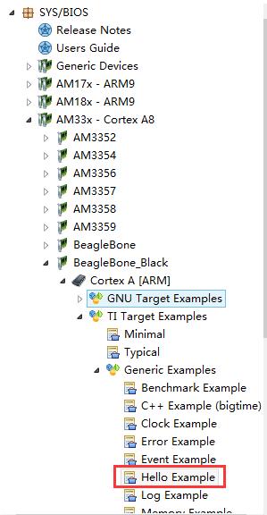
1. I imported the Hello Example from the TI Resource Explorer.
2. I have changed the .c file, which is shown below.
#include <xdc/std.h>
#include <xdc/runtime/System.h>

#include <ti/sysbios/BIOS.h>
#include <ti/sysbios/knl/Clock.h>
#include <ti/sysbios/knl/Task.h>
#include <ti/sysbios/knl/Semaphore.h>

#include <xdc/cfg/global.h>

#include "soc_AM335x.h"
#include "beaglebone.h"
#include "gpio_v2.h"

/*****************************************************************************
**                INTERNAL MACRO DEFINITIONS
*****************************************************************************/
#define GPIO_INSTANCE_ADDRESS           (SOC_GPIO_1_REGS)
#define GPIO_INSTANCE_PIN_NUMBER        (23)

/*****************************************************************************
**                INTERNAL FUNCTION PROTOTYPES
*****************************************************************************/
static void Delay(unsigned int count);

/*****************************************************************************
**                INTERNAL FUNCTION PROTOTYPES
*****************************************************************************/
void taskLedBlink(UArg arg0, UArg arg1)
{
    /* Enabling functional clocks for GPIO1 instance. */
    GPIO1ModuleClkConfig();

    /* Selecting GPIO1[23] pin for use. */
    GPIO1Pin23PinMuxSetup();

    /* Enabling the GPIO module. */
    GPIOModuleEnable(GPIO_INSTANCE_ADDRESS);

    /* Resetting the GPIO module. */
    GPIOModuleReset(GPIO_INSTANCE_ADDRESS);

    /* Setting the GPIO pin as an output pin. */
    GPIODirModeSet(GPIO_INSTANCE_ADDRESS,
                   GPIO_INSTANCE_PIN_NUMBER,
                   GPIO_DIR_OUTPUT);
    while(1)
    {
        /* Driving a logic HIGH on the GPIO pin. */
        GPIOPinWrite(GPIO_INSTANCE_ADDRESS,
                     GPIO_INSTANCE_PIN_NUMBER,
                     GPIO_PIN_HIGH);

        Delay(0x3FFFF);

        /* Driving a logic LOW on the GPIO pin. */
        GPIOPinWrite(GPIO_INSTANCE_ADDRESS,
                     GPIO_INSTANCE_PIN_NUMBER,
                     GPIO_PIN_LOW);

        Delay(0x3FFFF);
    }

}

/*
 *  ======== main ========
 */
Int main()
{

    // BIOS task setup
    Task_Params taskParams;
    Task_Params_init(&taskParams);
    taskParams.priority = 1;
    Task_create (taskLedBlink, &taskParams, NULL); // taskLedBlink

    BIOS_start();

    return(0);
}


/*
** A function which is used to generate a delay.
*/
static void Delay(volatile unsigned int count)
{
    while(count--);
}

/******************************* End of file *********************************/
3. I have included some necessary header file.

4. I have added some libraries.

5. I added post-build commmand
"${CCS_INSTALL_ROOT}/utils/tiobj2bin/tiobj2bin.bat" "${ProjName}.out" "${ProjName}.bin"
"${CG_TOOL_ROOT}/bin/armofd.exe" "${CG_TOOL_ROOT}/bin/armhex.exe"
"${CCS_INSTALL_ROOT}/utils/tiobj2bin/mkhex4bin.exe" & "${IA_SDK_HOME}\starterware\tools\ti_image\tiimage.exe"
"0x80000000" "NONE" "${ProjName}.bin" "${ProjName}_ti.bin"
6. I referred to e2e.ti.com/.../312951 and add the following code to the end of the .cfg file.
var Mmu = xdc.useModule('ti.sysbios.family.arm.a8.Mmu');
Mmu.enableMMU = true;

/* Force peripheral section to be NON cacheable */
var peripheralAttrs = {
    type : Mmu.FirstLevelDesc_SECTION, /* SECTION descriptor */
    bufferable : false,
    cacheable  : false,
    shareable  : false,
    noexecute  : true,
};

/* Define the base addresses in which the peripherals reside. */
/* Clock Module, GPIO0, UART0, I2C0 */
var peripheral0BaseAddr = 0x44E00000
/* GPIO1, UART1, UART2, I2C1, McSPI0, McASP0 CFG, McASP1 CFG */
var peripheral1BaseAddr = 0x48000000
/* GPIO2, GPIO3, UART3, UART4, UART5, I2C2, McSPI1 */
var peripheral2BaseAddr = 0x48100000

/* Configure the corresponding MMU page descriptor */
Mmu.setFirstLevelDescMeta(peripheral0BaseAddr, peripheral0BaseAddr, peripheralAttrs);
Mmu.setFirstLevelDescMeta(peripheral1BaseAddr, peripheral1BaseAddr, peripheralAttrs);
Mmu.setFirstLevelDescMeta(peripheral2BaseAddr, peripheral2BaseAddr, peripheralAttrs);
After building such project, I got the _ti.bin file. I renamed it as "app", then copied it to the SD card with Beaglebone Black bootloader(MLO). When board booted, I cannot see the LED to blink, the UART information stop at "Jumping to the application...".
Then I tried to modified the .c file as below.
#include <xdc/std.h>
#include <xdc/runtime/System.h>

#include <ti/sysbios/BIOS.h>
#include <ti/sysbios/knl/Clock.h>
#include <ti/sysbios/knl/Task.h>
#include <ti/sysbios/knl/Semaphore.h>

#include <xdc/cfg/global.h>

#include "soc_AM335x.h"
#include "beaglebone.h"
#include "gpio_v2.h"

/*****************************************************************************
**                INTERNAL MACRO DEFINITIONS
*****************************************************************************/
#define GPIO_INSTANCE_ADDRESS           (SOC_GPIO_1_REGS)
#define GPIO_INSTANCE_PIN_NUMBER        (23)

/*
 *  ======== main ========
 */
Int main()
{
    /* Enabling functional clocks for GPIO1 instance. */
    GPIO1ModuleClkConfig();

    /* Selecting GPIO1[23] pin for use. */
    GPIO1Pin23PinMuxSetup();

    /* Enabling the GPIO module. */
    GPIOModuleEnable(GPIO_INSTANCE_ADDRESS);

    /* Resetting the GPIO module. */
    GPIOModuleReset(GPIO_INSTANCE_ADDRESS);

    /* Setting the GPIO pin as an output pin. */
    GPIODirModeSet(GPIO_INSTANCE_ADDRESS,
                   GPIO_INSTANCE_PIN_NUMBER,
                   GPIO_DIR_OUTPUT);
    /* Driving a logic HIGH on the GPIO pin. */
    GPIOPinWrite(GPIO_INSTANCE_ADDRESS,
                 GPIO_INSTANCE_PIN_NUMBER,
                 GPIO_PIN_HIGH);

    // BIOS task setup
    BIOS_start();

    return(0);
}

/******************************* End of file *********************************/
Things didn't change, I cannot see the LED to be lighted, and the UART information stoped at "Jumping to the aplication".
Actually, I have no idea about it at all. Could someone please help me ? Is there any instruction or blog about it ? Or is there any project resource that I can get ?


