thanks for participating and thanks for letting me ask a question (or two).
with some help of electronic relating blogs and tutorials (such as Kynix http://www.apogeeweb.net/), i'm building a kiln controller using a controller module, solid state relay(s), and thermocouple.
i built the kiln i'm controlling and it is powered by (2) 110 volt lines coming from a double pole breaker with a ground to 4 switches wired in series for 4 elements.
being new to building a control system i inquired about the parts needed.
i was told that using one solid state relay on one of the 110 lines would
cut the circuit to the kiln. i'm thinking that isn't true and that i need a relay on each 110 line with both relays connected to the same connector/actuator on the controller.
concurrently, when i inquired about adding a second breaker inline after the relay, a single pole one was recommended. again, i think not.
so... any thoughts on this matter?
i believe my kiln pulls about 28 amps.
i have had the kiln for years. with glass kilns you need to be able hold a steady temp for 30-45 min or more at times and using 4 mechanical switches, as i have been doing, is definitely "old school".
so i researched what is needed and it appears to come to:
a digital temperature controller
a solid state relay
a thermocouple
i have purchased these items:
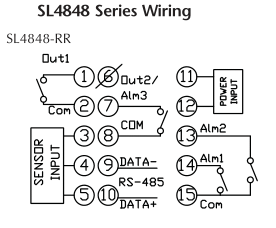
solo controller SL-4848-RR
solid state relay(AD-SSR640-AC-280A)
circuit breaker(WMZS1B40)
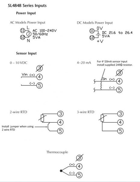
here are a couple wiring diagrams for the controller:
my understanding is that relay is a switch actuated by the controller.
i would like to add a secondary breaker close to the kiln.
i thought i would just cut the line and throw this stuff in.
the controller has a rs485 output for computers to have what is called a supervisory control and data acquisition human machine interface. scada/hmi
some interfaces can be very visually elaborate. like a web page can be.
well, that's about it in a nutshell...
thank you,
live long and prosper...


