This thread has been locked.

If you have a related question, please click the "Ask a related question" button in the top right corner. The newly created question will be automatically linked to this question.

TPD5S115: what is the maximum output current

Part Number: TPD5S115

Hi Sirs,

Sorry to bother you.

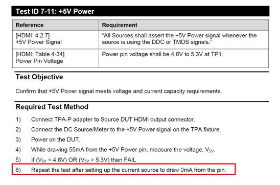
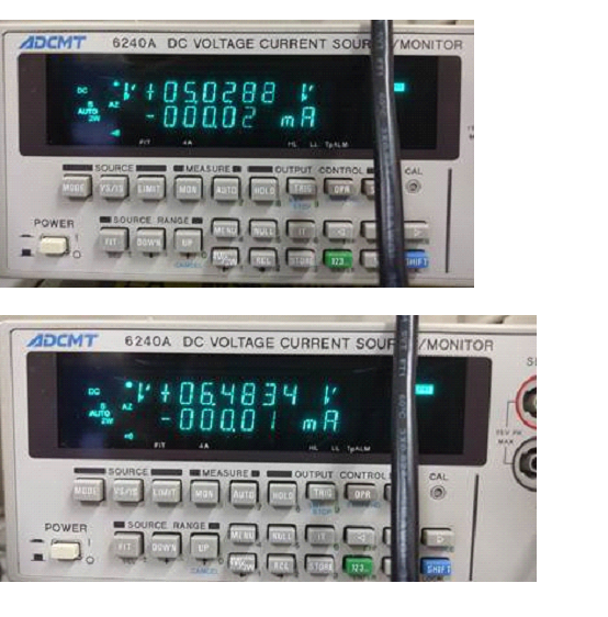
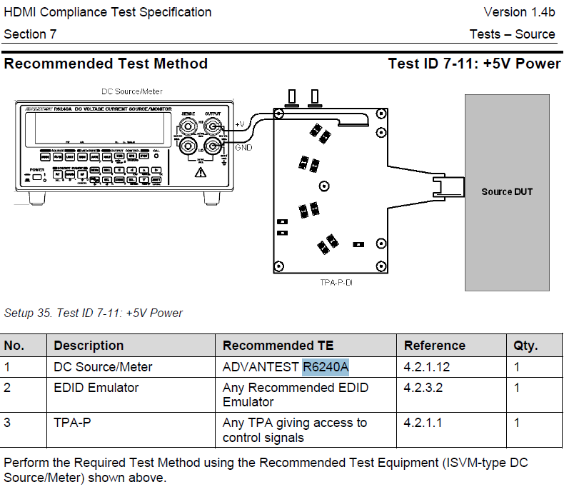
When we test HDMI CTS 7-11, we found if machine to load 0.02mA, the output will keep normal value 5.0288v. But if load lower than 0.01~0 mA, the output will be 6.483V. There will make 7-11 test result fail.

So, is this phenomenon is normal?

  • Hello,

    Can you please answer a few questions so I can understand your system well enough to assist you.


    Are you using the internal Boost regulator to generate the 5V supply?
    What is the status of the EN pini on the TPD5S115?

    Regards,
    Chuck
  • Hi Sirs,

    Thanks for your reply,

    Please refer my update as below.

    Are you using the internal Boost regulator to generate the 5V supply?

    We should used internal boost regulator since the VPH_PWR is 4.2V. Please refer to our application schematic as below.


    What is the status of the EN pini on the TPD5S115

    We are using 100Kohm pull-high to 1.8V on EN pin.

  • Hello,

    Based on your diagram, I cannot explain the behavior that you are seeing from the part. It appears that the boost converter is not properly regulating with zero load.

    Can you repeat the test with a 10uA load? I understand that this is out of spec,, but I am trying to gain visibility into why the boost regulator is not operating correctly.

    Has this behavior been observed on multiple units?
  • Hi Sirs,

    Please refer our update as below


    If use the electronic load then we can output HDMI 5V normally. Howerer, while we use test method according to CTS 7-11 and the current source draw 0mA, HDMI power become 6.4V then test FAIL?

    So does TI have CTS 7-11 test equipment?  

    If yes, could n you help verify this issue??


    Thanks!!

  • Hi Sirs,

    Update CTS 7-11 test and our result.

  • The meter shows that current is being driven into the part in both cases. You are showing negative current.

    Are you certain that the meter is properly calibrated.

    I know that it is showing current in the micro amp range, but current driven into the part can shift the voltage.
  • Hi sirs,

    The meter 6240A has been calibrated on Mar 01, 2018 and the next time calibration will be on Mar 01, 2019.

    Please refer to our experiment as below, seems the abnormal voltage only appear on our TPD5S115 circuit when drawing a 0.01mA. 

    If the current meter drawing the same 0.01mA from other HDMI source device, the device can output 5V normally.

    Could you help to review our schematic design to see if there is something wrong? Meanwhile, can you reproduce this issue on your lab if you have the CTS 7-11 test environment?

    Best regards,

    Jackson Hung

  • Hi Sirs,

    Please refer our update as below

  • Hi Sirs,
    Sorry for pushed , any suggestion on this?
    How could we clarify this is design or test method issue

    Thanks!!
  • Hi Sirs,

    Sorry for pushed, any update on this? or have any EVM can share for us to test?

    Thanks!!

  • Hi Sirs,

    Is there any further more info for this issue? 

    Please advise if any direction for next step, thanks for support.


  • Hi Sirs,

    We have recorded a video to show that how to reproduce 5V abnormal issue, please let us know your opinion if you can also reproduce this issue on your side? 

    Thanks!

    Jackson Hung

  • I have searched for an EVM for this part and it is not available, even internally.

    I am attempting to get one of the original characterization boards, but have not found one yet.
  • I have reviewed your results with the design team and we have no explanation for the behavior that you are seeing.

    Can you try adding a 500k Ohm resistor to the output of the boost converter so that it always sees a 1uA load and repeat your test?