This thread has been locked.

If you have a related question, please click the "Ask a related question" button in the top right corner. The newly created question will be automatically linked to this question.

HDMI to LVDS converter solution

Other Parts Discussed in Thread: SN75LVDS83B, TFP401, TFP401A, TFP410

Hi,

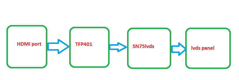
I want to convert the HMDI video output of a portable computer to a lcd panel which has LVDS. Decoding of the HDMI audio is not required. The display panel has lvds connector

The specifications of the panel  are as follows:

power supply: 3.3 v

size: 10.1 inch 

TFT/LCD

resolution: 1024x600

colors: 262K, RGB: 6 bit pixel data

pixel format: RGB horizontal stripe

LVDS connector: 40 pin, 1 channel

Please help me if there is any single chip solution, if not a two chip solution.

  • Hello, 

    There is a two-chip solution for your application.

    Please review the attached document.

    Regards.

  • I've gone through this document before.

    The display I'm using  has a 6 bit pixel data where as in the document talks about 18 or 24 bit pixel data for one channel LVDS connnector. 

    More over the block diagram in the document is dvi rx not hdmi. 

    I want to know if the DVI receiver IC mentioned in the document can be used to receive the hdmi.

    Can you please suggest the block diagram and the configuration for my requirements.

    Regards

    Arun Kumar

  • Hello Arun,

    The DVI receiver can decode HDMI video-only, if there is audio present on the TMDS stream, the DVI receiver will not be able to decode it, you mentioned before that you are not sending audio over the HDMI so the DVI receiver listed on the previous document will work.

    Regarding the 6-bit pixel, could you double check this, isn't it that your panel requires 6-bit per color making a 18-bit per pixel?

    Regards.

  • Hi,

    Thanks for the clarification. I want the schematic symbols and pcb package symbols to create a schematic diagram I downloaded the symbol and converted it to the eagle format. But the format is not not good. could you please provide me the symbols for eagle. If not please let me know for which schematic editor you have the symbols. I created the symbols for eagle using the ultra librarian, it created only the package symbols but not the schematic symbols.

    Please help me.

    Regards

    Arun Kumar

  • Hello Arun,

    Which part numbers do you want the symbols for?

    Regards.

  • sn75lvds83b

    TFP401

    TFP401A

    Also, the output pixel color data from TFP401 is 16 bit /color. Consider the Red color

    (QE[23:16])----->pin 30-37 and QO[16:23] ------->pin 69–75, 77 which is a 16 bit data/color.

    where as the sn75lvds83b accepts only 6bits/color. (see figure 15 of sn75lvds datasheet).

    Now my question is how should I connect the 16 bit/color (both even and odd) data bits coming from the TFP401 to the 6bit/color input of the sn75lvds83B.

    Can I leave the odd bits and only connect the even bits or i have to multiplex. What is the best solution for 6bit/color panel. 

    Regards

    Arun Kumar

  • Hello Arun, few things to mention:

    1) Actually, the TFP401 has 8-bit per color, QE[16:23] is a 8-bit array.

    2) If you look at the TFP410's datasheet, QE[16:23] is the output for even and odd red pixels in 1-pixel per clock, so the answer is yes, you can leave the QO[] outputs floating if you select 1=pixel per clock, in this configuration, the TFP401 will output the even and odd pixels on the QE[] bus in a tandem fashion, this is, first pixel 0 then pixel 1 and so on.

    3) Your configuration seems to be a 24-bit graphics controller to 18-bit panel, you can see the document at the below link for reference, the configuration in Figure 8 will fit your application.

    4) the bit ordering is critical so make sure your panel has the same bit ordering as the Figure 8 on the document.

    http://www.ti.com/lit/an/slla300/slla300.pdf

    And finally, unfortunately the schematic symbols available at ti.com are the only ones we have, did you follow the instructions to download the symbols?

    Regards.

  • Hi,

    Thanks for the information.

    I'm a bit confused with the figures 14 -17 in the sn75lvds data sheet. In the figures the sn75lvds is connected to the 12, 24,18 bpp gpu. But in my application i'm not directly connecting any gpu. I'm taking the input from the hdmi port of the device. 

    The above pic shows my intended application. In the figures 14-17 of the sn75lvds data sheet instead of hdmi port there is a gpu. 

    Which figure in sn75lvds data sheet should I consider for my design?

    How many bits does the hdmi port output? is it 18 or 22 or 24?

    Regards

    Arun Kumar

  • Hello,

    The HDMI port outputs a TMDS serial stream, the TFP401 de-serializes this  stream and converts it into a parallel output.

    The output of the TFP401 will represent the "GPU" on the figures of the LVDS datasheet.

    The TFP401 will output a 24-bit parallel word on the QE[] bus when it is set to 1-pixel per clock or will output a 48-bit parallel word on the QE[] and QO[] buses when it is configured as 2-pixel per clock.

    Regards.

  • I was wondering if there is a reverse device that can do LVDS to HMDI?


    Thank you!

  • Hello TI Lady,

    You can use the two-chip solution, SN75LVDS82/822 + TFP410. Check if they are compliant with your electrical specifications.

    Regards,

    Aldo