This thread has been locked.

If you have a related question, please click the "Ask a related question" button in the top right corner. The newly created question will be automatically linked to this question.

SN65LVDS324 etc / 16bit ~ 32bit , Transmitter , Receiver , 1.8V supply

Guru 20090 points
Other Parts Discussed in Thread: DS90C185
Hello,
 
I'm serching  Transmitter(serializer) and Receiver(desilializer) between  ASIC of Camera and LCD panel for our customer.
Please let me know the device which has the below requiremnt ?
 
<requirement>-------------------------------------------------------------------
-Vdd=1.8V
- IO Voltage=1.8V
-16bitYUV ~ 24bitRGB
-Receiver integrated Equalizer
-DCLK Frequency above 80MHz
-Low power comsumption : Tx + RX < 200mW
---------------------------------------------------------------------------------------
 
I think that SN65LVDS324 may be used their application.
But  I can find the receiver only.
 
Best Regards,
Ryuji Asaka 
 
 
  • Hello Ryuji,

        The SN65LVDS324 works only with specific image sensors (see the datasheet to verify compatibility).

        We have more transmitters/receivers, however if we restrict  VCC=1.8V, this lead us only the DSI options (see the SN65DSI8x devices) and we only have the transmitters (at least wit the devices in our group). Please give me until Tuesday to seek deeper and try to find any better solution.

    Regards,

    Diego.

  • Hello Diego san,
     
    Thank you for the reply.
    I wait the information until Tuesday.
     
    Best Regards,
    Ryuji Asaka
  • Hello Ryuji-san,

        Unfortunately We don't have in our group the exact solution you need. So I will move your post to the High speed interface forum, maybe  you will find a better solution there. 

    Best regards,

    Diego.

  • Hello High Speed Interface member,
     
    Are there Transmitter(serializer) and Receiver(desilializer) between  ASIC of Camera and LCD panel ?
    Please see the customer requirement as following.
     
     
    <requirements>-------------------------------------------------------------------
    -Vdd=1.8V
    - IO Voltage=1.8V
    -16bitYUV ~ 24bitRGB
    -Receiver integrated Equalizer
    -DCLK Frequency above 80MHz
    -Low power comsumption : Tx + RX < 200mW
     
    If the device don't have above few requirement , it is OK.
    Please let me know the device closest to the above requirements.
    ---------------------------------------------------------------------------------------
     
     
    Diego san,
     
    Thank you for the checking.
     
    Best Regards,
    Ryuji Asaka
  • Hello,

    We don't have LVDS serdes with Vcc=1.8, however, we do have serdes with I/O levels adjustable from 1.8V to 3.3V, if you can set your VCC=3.3V then you could use them.

    Visit the below link form more information.

    Regards.

    http://www.ti.com/lit/an/slla300/slla300.pdf

  • Hello Elias san,

    Thank you for the information.
    I will infrom these device.
     
    I could find DS90C185( serializer ) Vcc=1.8V device.
    Are there any plan of deserializer which pair of DS90C185 ?
     
    Best Regards,
    Ryuji Asaka


  • Hello Asaka-san,

    the DS90 devices are supported on the High Speed Interface Forum, I could move this post to that forum but since it is labeled with "LVDS324" it will be moved back here so I recommend you to create a new forum post on the High Speed, here i the link http://e2e.ti.com/support/interface/high_speed_interface/default.aspx 

     I'm sure you will find what you need there.

    Regards.

  • Hello Ellias san,
     
    Thank you.
    I understood.
     
    Best Regards,
    Ryuji Asaka
  • Hello:

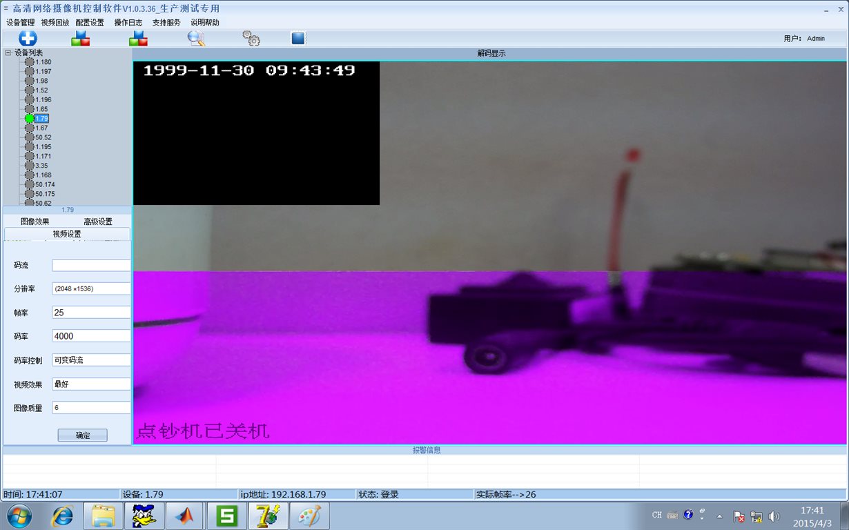
         We also used the structure design of Aptina Sensor + AR0331 SN65LVDS324 + 8127 CPU the adapter plate. But I don't know if the FFC cable is too long or what reason lead to our side, flashing video always have purple stripes, and are electrically in the boot, there have been 8127, restart, or soft reset, no, but reading the SN64LVDS324 value had not found error!

       The video screenshot as shown below:


       whether you can provide some suggestions ?

      Thanks !

      Best regards,

      Fish Yu.

  • Hello Fish,

    Have you tried to restart the SN65LVDS324, also could you describe the debug process you follow so far?.

    Regards,
    Diego.
  • Hello  Diego Cortes:

          We have tried to restart the SN65LVDS324, when the Purple image problem is happen. it can Recovery ,and return to normal. Is it possible that the PCB has a signal timing problems between SN65LVDS324 and DSP processor , leading to this situation ? The FFC cable between SN65lvds324 and dsp 8127 is up to 5-7cm.

          First, the system crashes, after a long-running. We suspect that the sn65lvds324 chip is dead,so we couldn't read the configure data from it.

          Then,we add a MCU in Interface Board to control it Individually .And we set aside the previous connection !

          But this issue is happen whether it is previous scheme or the plan with MCU.

          The Purple image problem is happen when  several  power on .

    Thanks!

     Regards,
     Fish Yu

  • Hello Fish,

    Which sensor are you using?, Could you measure the jitter on the input clock ?, Also please take a look on the note of the datasheet page 9.

    Regards,
    Diego.
  • Hello Diego Cortes :

            The sensor we used is  Aptina AR0331, It outpout the Pixel data  to  SN65LVDS324 through SubLVDS.

  • Hello,

    Could you try the following power up sequence and verify that the issue is gone?


    1)      Power up the system but keep the sensor in low power mode and the SN65LVDS324 with the RST terminal asserted (tied to low).

    2)      De-assert the RST terminal on the SN5LVDS324.

    3)      Configure the SN65LVDS324 in the following order:

                                     i.            Write 0x03 to the register 0x28.

                                   ii.            Configure the registers 0x09 – 0x0E as you need .

                                  iii.            Configure the registers 0x1F – 0x22 as you need.

    4)      Put the sensor onto stream mode.


    Best regards,

    Diego.

  • Hello Diego:
    Thanks for you advice,And I will have a try next Monday.
    The Process we initialize peripheral is that:
    1. We reset the Sensor and configure it .
    2. Delay 7 seconds ,we tied the RST of sn65lvds324 to low, maintain it 2s.
    3. then Configure the registers 0x09 – 0x0E. Others is keep default Values.
    The Register Value we configured , is right by reading through I2C we know!


    Best regards,
    Fish Yu.
  • Hello  Diego Cortes:

            Thanks for your reply last week. I have try your suggestion morning, And find that issue is still gone! 

            It is Lower probability for those sample using FFC cable connect the interface board with DM8127 System board, than using wire cable!  About 20 timesPower on,Or 40 times DM8127 reset, The Flashing purple stripes will appear. We attributed to hardware line interference! 

            We  reset Sensor at first through I2C By MCU, and  wait the signal from DM8127 which have complete configure Sensor. Then , MCU deploy the data in SN65lvds324. It detects and configures Infinite loop!


          Best regards,

          Fish Yu

  • Hello Fish,

    Could you measure the jitter (Rj, Dj & Tj) on the input clock of the SN65LVDS324?

    Regards,
    Diego.
  • Hello Diego:

              Thanks for your suggestion ! The Input clock of the SN65LVDS324 is  work on common differential mode. We measure the SCLK waveform using Oscilloscope ,and find the frequence is slew when it work correctly! 

           Regards,
           Fish Yu.