This thread has been locked.

If you have a related question, please click the "Ask a related question" button in the top right corner. The newly created question will be automatically linked to this question.

TUSB8041 Not recognized by Windows 7

Other Parts Discussed in Thread: TUSB8041, MSP430F5659, MSP430F5529

Hello!

I have a design in which I'm using the TUSB8041 chip as the controller for a 3 port usb hub; one downstream port is connected to an MSP430F5659 that is also present on the board, and the other two downstream ports are connected to USB-B connectors; I have attached a schematic of my design to hopefully make things a little more clear.

Whenever we apply power to the board, however, we are not able to see the hub in device manager, nor are we able to see any devices that are plugged into the hub.  The design was copied from the most part from the EVM reference design (sllu198), so we aren't sure what could be the problem.  The board is definitely receiving power, and I was able to see some sort of periodic clock-like pulse on the USB 3.0 RX lines coming from the computer into the TUSB8041.

USB Hub Eval 1.0 Rev B.sch.pdf Any sort of help would be greatly appreciated!

  • Hello Simran,

    The TUSB8041 is not intended to be used as a bus-powered hub. If this is a closed system where the power provided on VBUS exceeds normal USB specifications, the application will work but you will need to confirm that an adequate reset is received on the GRSTz pin and that the VBUS source is able to drive the load without drooping.

    A few other notes:
    On the downstream ports, the series capacitors should be on the TX pair, not the RX pair. USB 3.0 won't work otherwise.
    There should be pull-ups on SDA and SCL if the I2C interface is to be used. If it is not used, do not install the EEPROM - the TUSB8041 will attempt to load registers from the EEPROM and enter programming mode.

    Post again if you are still having difficulty.

    JMMN
  • Hi JMMN,

    Thanks for the reply! For our application of this chip, we are required to have it be bus powered; the device that we are developing is meant to be used out in a field, away from any sort of wall-power; with that said, we have made sure that we won't be exceeding the power limits of the USB specifications.

    In the current implementation of the board, we are measuring around 300mA being pulled by the device. What sort of signal should we be seeing on GRSTz to confirm that a reset is being received properly?

    To address your other points: The capacitors are actually on the TX pair on the real board; having them on the RX pair is a schematic error that has been addressed internally.
    Originally we did plan to use an EEPROM, but for now we are focusing on just trying to get this IC to work first.

    Thanks for your help,

    Simran Singh
  • Hi Simran,

    Please make sure that the voltage rails are not dipping low at power on and that the GRSTz is held low for at least 1-2ms after the 1.1V and 3.3V rails are ramped. Please note that each downstream USB 3.0 port is expected to provide 900 mA. 3 ports @ 900 mA, plus the power consumed by the TUSB8041 will exceed the USB specification for VBUS power consumption.

    Has the EEPROM been removed if it is not being used? Can you confirm that the TEST pin is low and the SMBUSz pin is high?

    JMMN
  • JMMN,

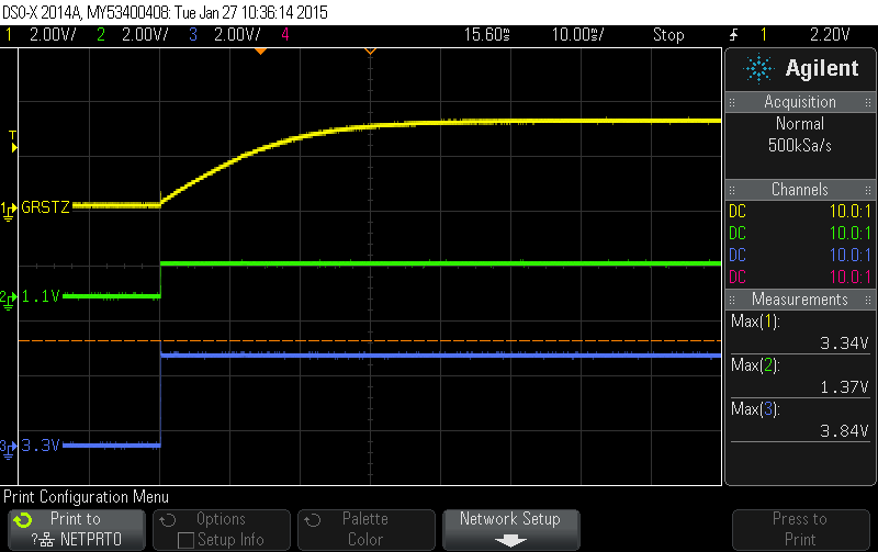
    I've attached a picture of the start-up cycle of the device; it seems to follow the guidelines of section 8.6 of the TUSB8041 datasheet.  If there is anything else that I could provide to help with this problem, feel free to let me know.

    Regards,

    Simran Singh

     Hello again 

  • Hi JMMN,

    GRSTz is held low for about 3.5 ms after the power rails are ramped up. I would assume that the device would still be recognized if the total current being used is kept under the limits set in the USB specification; if I am mistaken here, then that would be helpful to know.

    The EEPROM has indeed been removed from the board; the TEST pin is indeed low, and the SMBUSz pin is high upon power-on.

    Simran
  • Can you check to see if the crystal starts oscillating? Also, what are the voltages at pins 48 and 64? Can you check device manager to see if anything is loading when the hub is connected?
  • It appears as though the 24MHz crystal may not be oscillating. When I attach one end of our oscilloscope probe to a pin of the crystal, and the other end of the probe to ground, all we are able to measure is basically noise; there is no typical sinusoidal signal coming from the crystal.
    The voltage at pin 48 is 0.4917V, and the voltage at pin 64 is 0.5029V.
    Nothing appears in device manager whenever I connect the hub to my PC; likewise, there are no changes whenever I disconnect the hub from the computer.

    Just want to mention that your help is very much appreciated! I would be completely lost without the guidance you are providing.

    Simran
  • Hi Simran,

    Ok, this could mean an issue with the crystal circuit or the upstream port connection. You could try removing the 1M resistor to see if that helps.

    To lower power consumption, the crystal won't start unless there is an upstream connection. Can you confirm that all the connections are made upstream and VBUS > 4.8V? Can you probe DP and DM and check the line states?
  • Hi JMMN,

    I will try and remove the 1M resistor and see if that helps things; I will report back with the status after I have done that.

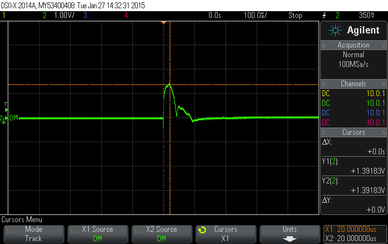
    The upstream connections are present, and VBUS is reporting as 4.991V.  The DP and DM lines show a quick pulse up to ~1.4V or so, and then settle back down to a low state of about 25mV; the pulse lasts for about 90us.  I have attached pictures to show how the lines look upon power-on.

    The DM line:

    The DP line:

    Thanks for your help,

    Simran

  • Hi again JMMN,

    Removing the 1M ohm resistor did not fix the problem; could it possibly be my capacitor values, or the fact that I am probing the crystal that might be causing the issues?

    Thanks,

    Simran
  • Hi Simran,


    Can you provide a part number for the crystal?  What about a schematic for the upstream connection? 

    Thanks!

  • Hi JMMN,

    The part number for the crystal is ECS-240-8-30B-CKM

    I've attached a screenshot of my schematic here.

    Let me know if there is anything else that might help!

    Thank you,

    Simran Singh

  • Hello JMMN,

    After some quick thinking, my team and I were finally able to get the crystal to work! Unfortunately, we now have another issue. It appears that the TUSB8401 is now constantly trying to communicate on the I2C lines, even after we removed the EEPROM. One thing to note is that we do have an MSP430F5529 also present on the I2C lines, although it is currently set for all of its pins to be hi-Z. Could there be something else that we might be missing here?

    Simran
  • Yet another breakthrough! The TUSB8041 now only polls the I2C interface once, and then stop after sending the one address byte across the lines. After that though, the device still doesn't get picked up by Windows. I feel like this is very close to being usable, but there is something that is causing it to still not be working entirely correctly.
  • Check to see if it appears in Device Manager as a Programming Endpoint.
  • This may not help, but I was surprised to find that the crystal does not oscillate if no upstream port is connected. This caused me a few hours of headscratching. Also, I found that a 2pin crystal with < 50 Ohms works the best - we were using a 4 pin and due to some semi-creative (i.e. fouled up) routing on the crystal (rated as 24 Mhz 30ppm, 18pf) worked fine.

    WRT to the EEPROM, I'm not using one, and you really don't want to have pullups on the I2C lines.