This thread has been locked.

If you have a related question, please click the "Ask a related question" button in the top right corner. The newly created question will be automatically linked to this question.

TUSB1310A not de-asserting PHY_STATUS after power -on reset de-assertion.

Other Parts Discussed in Thread: TUSB1310A, TUSB1310

Hi,

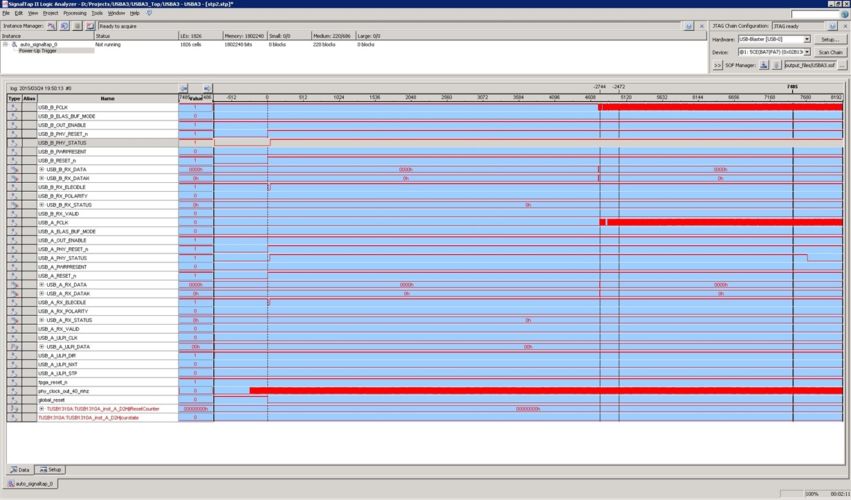
I have two identical prototype boards that have difficulties resetting the TUSB1310A parts. Each board has two TUSB1310A's but only one of the TUSB1310A's on one of the boards de-assert PHY_STATUS after coming out of reset. Only this instance of the TUSB1310A can receive data so it is certain that a bad reset is to blame.

Could you please check the attached Altera Signaltap trace to see whether anything stands out? I have spent a whole day debugging this, trying to tweak things but to no avail.

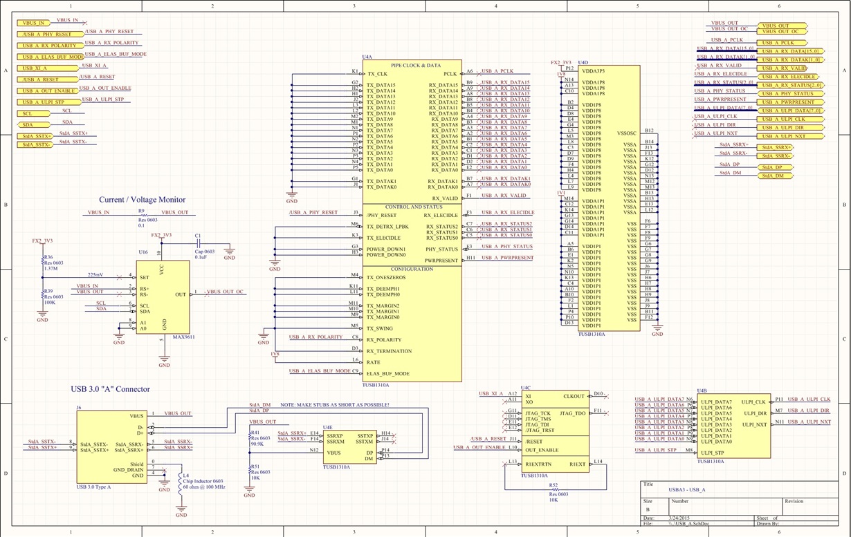
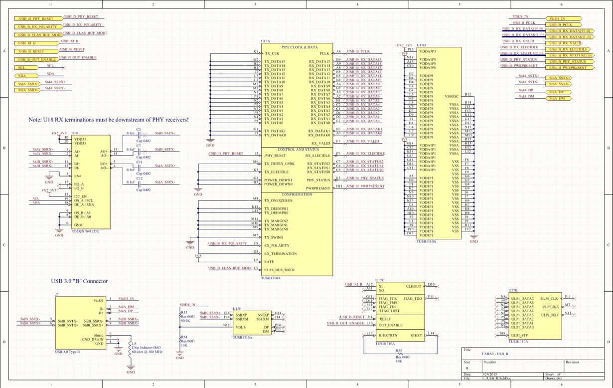
Note that only the RX path is used since this is for a USB 3.0 protocol analyzer design. Also, some pins are hard-coded per the attached schematics.

Thank you, /John.

  • Note that I'm using a 20 MHz reference clock (ULPI_DATA = 8'h00).
  • Hello,

    Which one is having the issue, the one with the USB type-A or the type-B ?
    Make sure PHY_MODE terminals are connected as described on datasheet.
    Make sure you are not trying to do an invalid power state transition(for example an invalid transition is P3 to P2).

    Can you elaborate more on the implementation, where are the StdA_SSTX signals coming from?
    Does the USB2.0/ULPI interface work?

    Regards
  • Hi Elias,

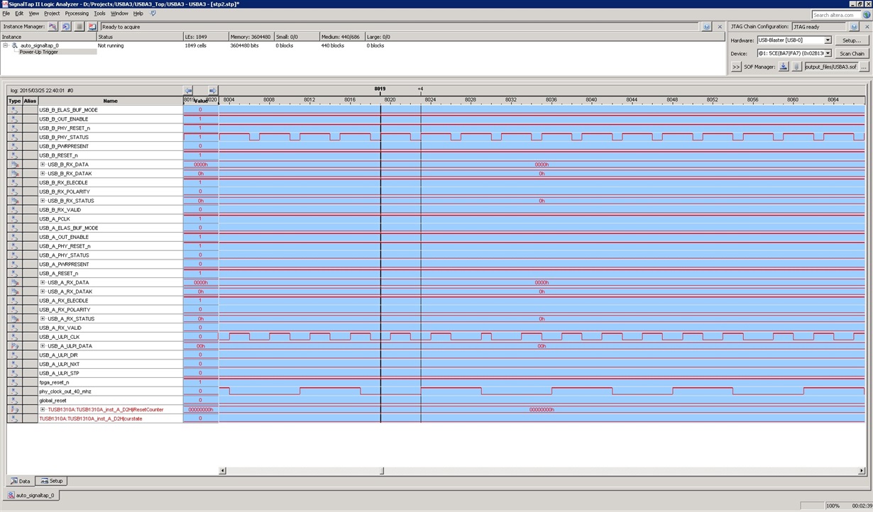
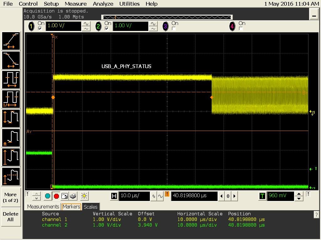
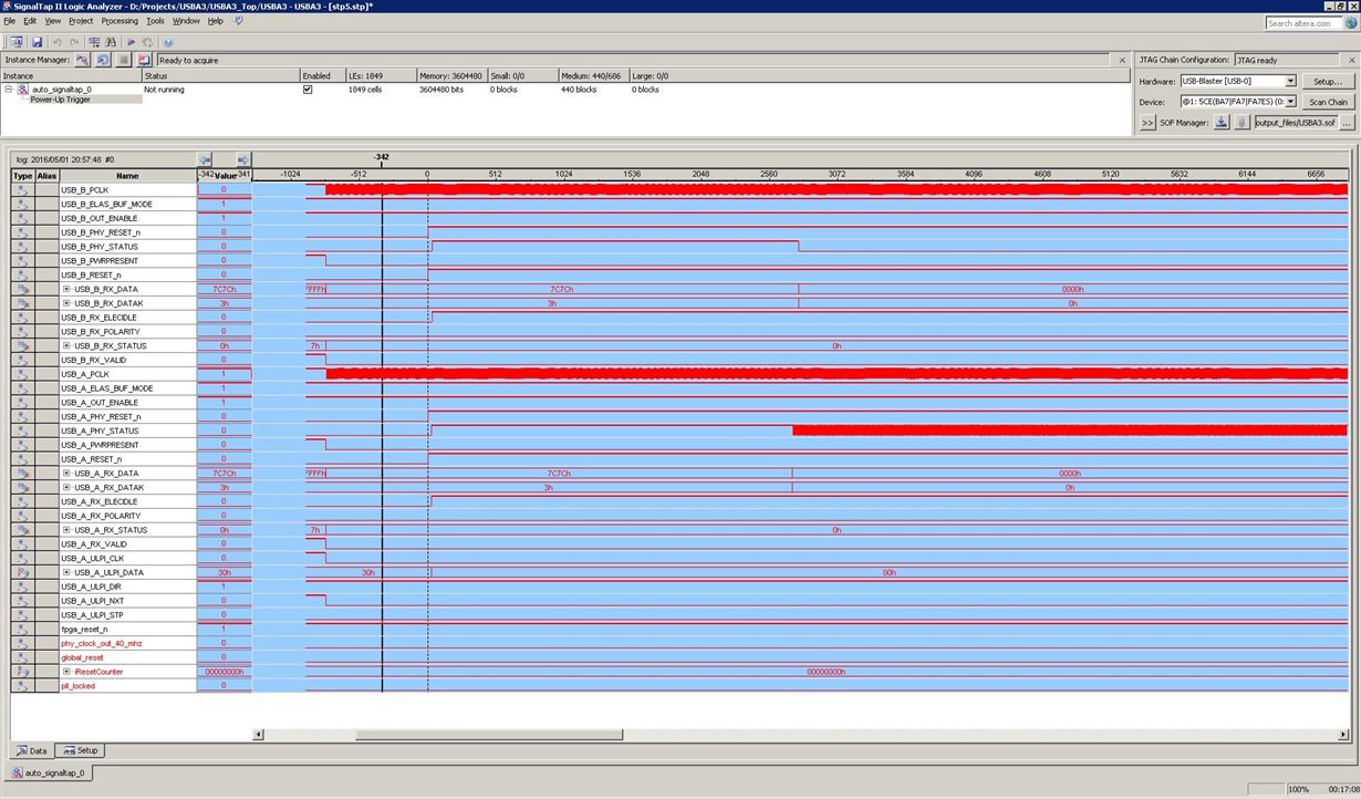
    The only PHY that works is the 'A' PHY on one of the two boards. The working PHY is correctly deasserting the PHY_STATUS signal some time after reset and once PCLK is valid. This can be seen in the top Altera SignalTap waveforms in my initial post.

    Like the schematics show, both PHYs are hard-wired to P0.  The PHY_MODE[1:0] pins are not connected since they are internally [PD:PU] by the TUSB1310A.

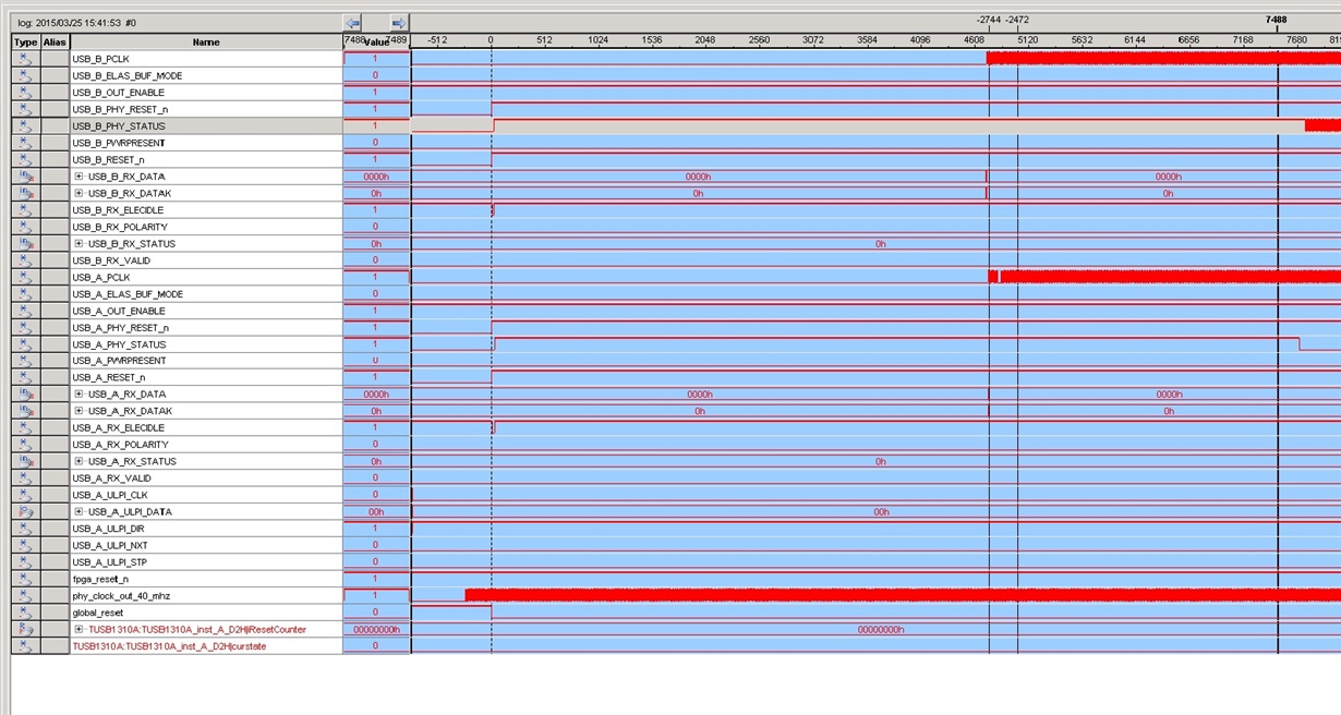
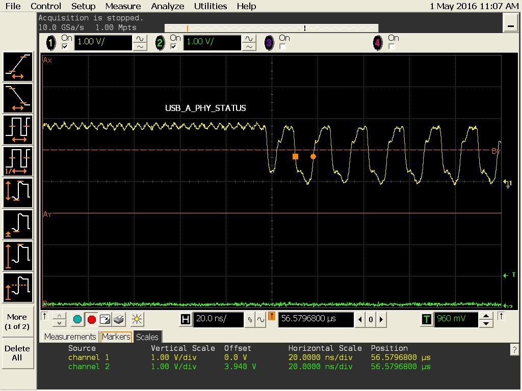
    I have today found something interesting; When changing the FPGA PHY_STATUS inout pin configuration to input (Verilog), I'm seeing that the USB_B_PHY_STATUS starts toggling apparently randomly around the same time it should be deasserted. Please see attached, new signaltap trace. It could be that the PHY for some reason doesn't sink the signal properly?

    Please disregard the SS signals for now. The primary goal is to make the reset work. I have not attempted to bring up the ULPI link yet.

    Thanks,

    /John.


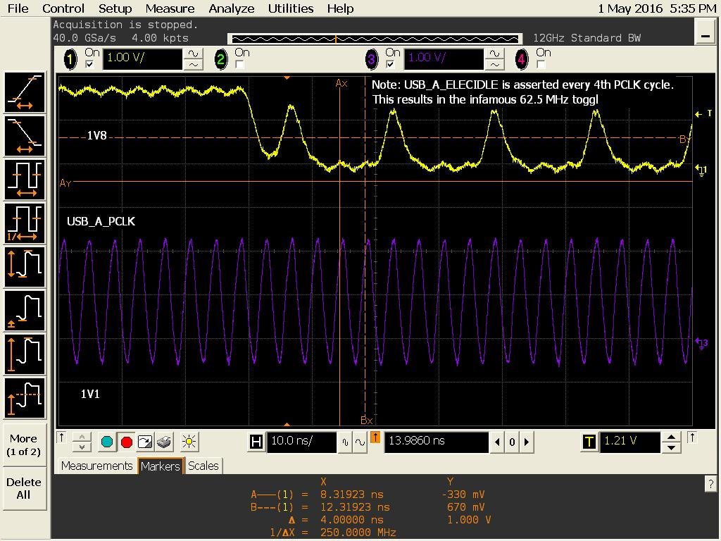
    NOTE: A zoom-in of the above USB_B_PHY_STATUS shows that it is toggling at a frequency 1/4 of PCLK (62.5 MHz). 3 PCLK cycles high and 1 PCLK cycle low per USB_B_PHY_STATUS period. Please see below zoom-in. What can cause PHY_STATUS to behave this way?


  • Hello,
    Some comments from the designer.

    1.
    “JTAG_TRSTN - . An external pull-down is required for normal operation.”
    ..but I don’t see a pull down on JTAG_TRSTz
    2. Normally an analyzer would need to detect a receiver before attempting to recover data. How do they do that without using the transmit interface at all?

    Regards
  • I can't get to the JTAG_TRSTN since not connected under the BGA.

    I've seen multiple posts where you recommend external PD to be used on the JTAG reset. No one has reported any issues being fixed by doing this. The datasheet says that an internal PD is used on this pin. What exactly, does the JTAG_TRSTN have to do with the PHY_STATUS?

    The receiver does not rely on the transmitter to recover data. All it needs is data lock. The TUSB1310A will recover the data and clock as soon as a proper RX SS signal is present.

    I have today found something additionally interesting: I noticed that the ripple on the 1V1 power rail was a bit high (9% while data sheet says max 5%). By lowering the input voltage to my switched regulators I managed to lower the ripple to around 6%. This made the USB_B_PHY_STATUS on board #2 to actually de-assert.

    It is possible that this is caused by the TUSB1310A detecting not good power? Could that be a reason for PHY_STATUS not to de-assert after de-asserted reset? How sensitive is the analog 1V1 power rail to noise? Have you noticed similar issues with noisy power rails?

    EDIT: It turned out that I introduced noise via my passive probe's ground loop. With an active probe, the power supplies are quiet. However, is there an issue with tying together digital and analog ground and power? Our thinking is that since the power supplies are designed for less than 5% ripple, both analog and digital max ripple is met and so the planes/power rails were tied together to save space/cost.


  • I still have not resolved this issue. I have tried all combinations of strapping, multiple versions of reset assertion and deassertion timing but to no avail. I have spent four whole days trying everything, read everything in this support forum etc.

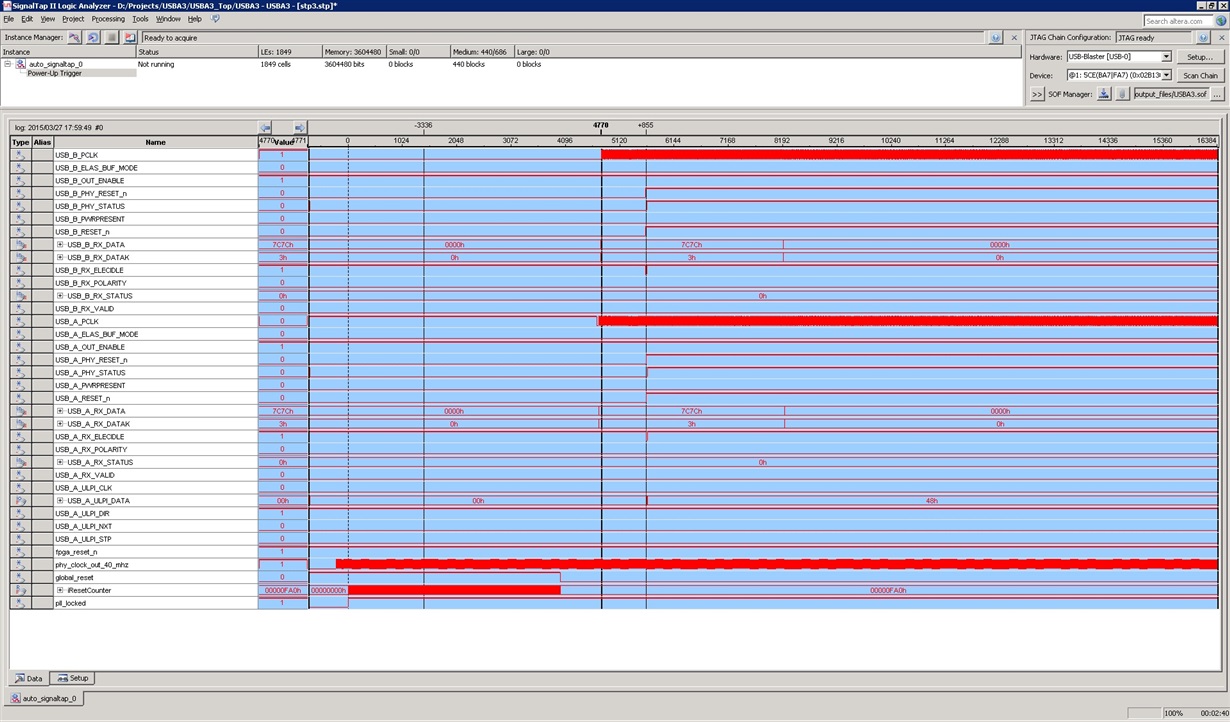
    Please find attached a couple of Signaltap traces where it is showed that it doesn't matter whether reset is applied before or after PCLK is good. PHY_STATUS does not deassert when it should.

    Note the 7C7C data output by both PHYs. When the data again changes to 0000, the PHYs should lower PHY_STATUS but it is not done.

    Also note that PCLK is generated although both reset signals are asserted.

    Overall, the behavior of the chip is highly erratic. Could you please check with someone within TI that might know what the 7C7C code means?

    Could you reproduce the behavior in-house?

    As things stand now, it looks like we can not use the TUSB1310A in our design. Is there a FAE that can work with us to get this to work?

    Note in the second picture that the ULPI clock is generated before reset but not after. This behavior is random, possibly related to the order which the power rails are turned on. Also note the toggling of USB_B_PHY_STATUS. Overall, completely flakey behavior.

    Thanks.

  • Hello,

    I am working with the designer to understand what the 7C7C means.

    I wouldn't recommend tying digital and analog power together.
    JTAG_TRSTN left floating could cause the Device to enter in test mode which will cause an erratic behavior, there is a chance that this is happening based on your power isolation problems.

    Regards
  • Isolating power rails are not needed as long as the maximum ripple specs are not exceeded. All rails on my board are properly designed with regards to PI to have at most 5% ripple on any rail (digital as well as analog). I doubt power integrity is to blame for this issue. Especially since I'm currently are powering all rails from an external bench supply which is very quiet.

    7C7C means electrical idle K symbol.

    I don't see how an external resistor can improve JTAG_TRSTN signal level. It is currently unconnected and your internally pull-down should definitely pull down to a valid low level since nothing else externally is causing signal contention. If you disagree, please give me a technical reason why additional pull-down is needed.

    Note that I'm unable to get to the JTAG pins since not connected under the TUSB1310A BGA.

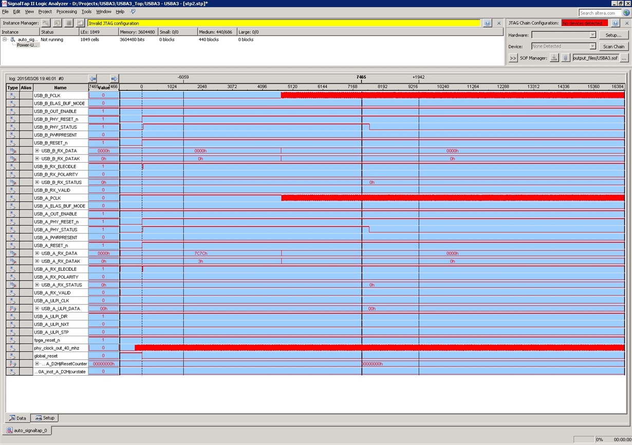
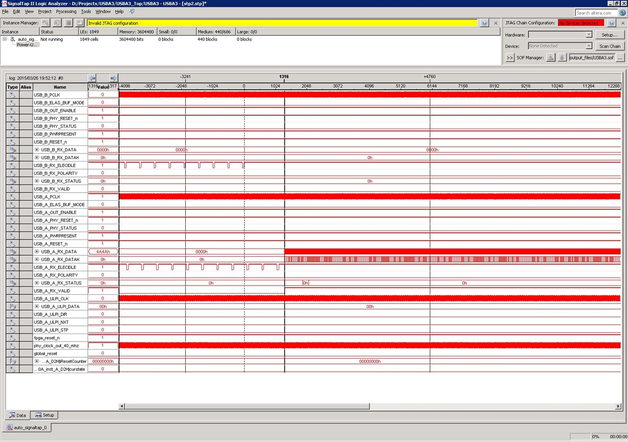
    Please note that one PHY actually works just fine on one of the boards. This is the "A" PHY shown in the below signaltap traces.  The "B" PHY mostly does not deassert the USB_B_PHY_STATUS signal although below actually does (PHY A always works, PHY B never captures data). On my 2nd board, none of the PHYs capture data correctly.

    The attached signaltap traces show that PHY A resets correctly and is able to capture data received. PHY B likely does not reset properly and consequently does not capture data properly. The PHY_STATUS and failed capture surely are closely related.

    Note that the "B" PHY does not output 7C7C while the "A" PHY does. This is also not consistent behavior.


    Note in the below signaltap trace that PHY A first receives LFPS and then the beginning of the initial TSEQ received. PHY B also receives LFPS but fails to receive data. The failing PHY B is likely related to PHY not outputting 7C7C in the above image.

  • I have today made lots of experiments. I have concluded that in about 50% of the cases where my board is power-cycled it actually works correctly. Both the "good" and "bad" scenarios show the same power rail sequence. Perhaps it is one of the floating pins (that should have PU/PD per the datasheet) that ends up in the wrong state.

    In some of the cases, the RX_ELECIDLE is outputting a square-wave with 62.5 MHz (1/4 of PCLK). This appears to happen when SS RX data is passed to the PHY "B" that does not initialize itself properly (PHY_STATUS doesn't assert after de-asserted reset). Could you please check under what circumstances 62.5 MHz is output from RX_ELECIDLE? This might give some leads. Note that the frequency stated by the scope is not correct. Ch2 is 62.5 MHz and Ch3 is 250 MHz.

    Note: Ch1: RESETN, Ch2: RX_ELECIDLE, Ch3: PCLK

  • I will purchase a BGA rework station so I can remove the failing PHY. I will then tie JTAG_RESETN to GND, PHY_MODE1 to GND and PHY_MODE0 to 1.8V. Finally, I'll solder the TUSB1310A  back onto the board.

    Since this is hard to do, I want to avoid redoing multiple times.

    Are there any additional potential suspect signals you feel should be strapped high or low?

    Thanks,

    /John.

  • Hello,

    I have double-checked with Design and JTAG_TRST definitely requires the external pull-down, leaving it floating could cause some internal PD/PU not be configured correctly.

    Regards

  • I have now confirmed that tying JTAG_RSTN to GND does absolutely nothing to improve the situation. The behavior of the chip is the same as previously described.

    I essentially, removed the BGAs, reworked the BGA site by adding 10mil tracks between key BGA pads to 1V8 or GND (as needed) and finally re-flowed new PHYs in-place. No improvement at all.

    I have found one more clue that seems relevant: The R1EXT/R1EXTRTN voltages sometimes appear incorrect and causes the PHY not to initialize when later reset by the FPGA.

    Half of the times my board is powered the PHY correctly deasserts PHY_STATUS after RESETN is deasserted. In this case, the voltage on R1EXT = 0V, R1EXTRTN = 0V before my FPGA is loaded and the PHYs are reset. After the FPGA is loaded and PHYs are reset the corresponding voltages around the 10K calibration resistor are R1EXT = 518 mV, R1EXTRTN = 5.2 mV. This appears to be the correct behavior since the PHY always initializes correctly and deasserts PHY STATUS when the board powers up with the 0mV/0mV R1EXT voltages.

    Now, sometimes, the PHY measures 2.4mV/518mV when the board is powered on. In this scenario, PHY STATUS is never deasserted after deasserted reset. Surely the TUSB1310A must enter some incorrect state, which the R1EXT voltages are symptoms of?

    Please ask the chip designer under which circumstances the voltages across the calibration resistor is non-zero after power-up. Please also ask what the purpose of the calibration resistor is.

    Thanks.

  • Hello,

    Yes, there could be a problem when hardwiring to P0.

    Per the spec:

    "1.1 Reset

    When the MAC wants to reset the PHY (e.g.; initial power on), the MAC must hold the PHY in reset until power and CLK to the PHY are stable.  The PHY signals that PCLK is valid (i.e. PCLK has been running at its operational frequency for at least one clock) and the PHY is in the specified power state by the deassertion of PhyStatus.  While Reset# is asserted the MAC should have TxDetectRx/Loopback deasserted, TxElecIdle asserted, TxCompliance deasserted, RxPolarity deasserted, PowerDown = P1 (PCI Express mode) or PowerDown = P2 (USB SuperSpeed Mode), TxMargin = 000b, TxDeemp = 1, PHY Mode set to the desired PHY operating mode, and Rate set to 2.5GT/s signaling rate for a PHY in PCI Express mode or 5.0 GT/s for a PHY in USB SuperSpeed 3.0 mode.  The state of TxSwing during Reset# assertion is implementation specific.  RxTermination is asserted in USB SuperSpeed 3.0 mode."

  • Could you please check with the chip designers under what circumstances the below abnormal behaviors could happen? It is impossible to test other power states than P0 since hard-coded on my board. The FPGA has no control over these lines. The usage is not common since I need the PHY to be fixed in P0.

    We need to work backwards from the symptoms and look inside the chip to see what state of the chip could cause the externally observed behavior. This is not an easy one to fix since I've spent a good whole month on this issue.

    Observed behavior:

    1) PHY_STATUS not deasserted after reset (happens about 50% of the time on one board).

    2) RX_ELECIDLE toggling with 62.5 MHz.

    3) Voltages around external calibration resistor 2.5mV/500mV rather than normal 0V/0V after power-on (before PHY is reset by FPGA).

    We really need to get insights from the chip designers to understand exactly what causes this. Given the easily reproducible symptoms, it should be straight-forward to look inside the chip to see what the potential causes could be.


    Thanks,

    /John.

  • Hi,

    I have now spend considerable effort debugging this issue. I have created a brand new daughter board that I can connect to my Altera Cyclone IV GX Development kit via the two HSMC connectors. The HSMC board contains the two TUSB1310A PHYs, separate pull-up or pull-down resistors (optionally installed) for all signals, separate headers allowing all signals to be scoped etc. I have tried reset to P2 power state as well as using both oscillator as well as crystal. In all cases, I'm still seeing that the de-assertion of the PHY_STATUS is not reliable.

    Could you please email me so I can send supporting material off-line? This new "TUSB1310A Debugging Board" will allow me to test anything you might suggest and capture scope and logic analyzer data for feedback.

    Thanks,

    /John.

  • Hello,

    you can send your information to elias.villegas@ti.com

    Regards

  • After much debugging and an additional board spin, I can confirm that the TUSB1310A does not work with an external oscillator. The only way it reliably resets is when using an external crystal. Can you confirm that this is a known issue? I have measured my clock jitter and it is very low (some 50 ps) per datasheet requirements. I will go ahead and continue working with an external crystal but it would be very interesting to know why the external oscillator input doesn't work properly since this has taken 6 months of painstaking debugging...
  • Hi John,

    Have you connected all TI Phy's signal or driving all ? Because before 2 days I had same problem with my TI phy chip, but I solved it with the use of on chip oscillator as phy ref clock(40 Mhz) and ULPI data line with strapping option (ULPI DATA5 and ULPI DATA6 for select input reference clock frequency for on chip oscillator).

    Try below logic for ULPI data Lines..

        logic [7:0] u20_data;
        assign u20_data = u30_ulpi_dir ? 'z : '0;
        assign u30_ulpi_data = reset_n_o ? u20_data : 8'b00110000;
        assign u30_ulpi_stp = 1'b0;

    Let me know if you still have any problem..

    Best Regards,

    Trupesh Vasoya

    Engineer | System Level Solution Pvt(I) Ltd

  • One year later, I still have not reliably solved the issue! I though the issue went away but, out of the blue, for a new board spin, the issue came back.

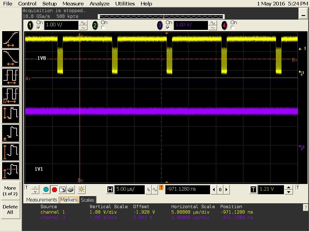
    The issue manifests itself in that PHY_STATUS either does not deasserts at all after reset or that it toggles every 4 PCLK cycles (62.5 MHz). Please see attached images 4, 5. When in this state, the PHY does detect LFPS (RX_ELEC_IDLE goes low periodically) BUT the same toggling goes on within the low pulses. The toggling exactly lines up with every 4th PCLK cycle. Please see attached images 17, 19. Please note that the top annotations in images 17,19 are incorrect, the top trace is RX_ELECIDLE.

    I have scoped all strapping signals (40 MHz crystal) and they are correct. Note that PHY B in the STP trace is configured exactly the same way as PHY A and it works the majority of the power on cycles (but not always). I have tried to replace PHY A, without any improvement.

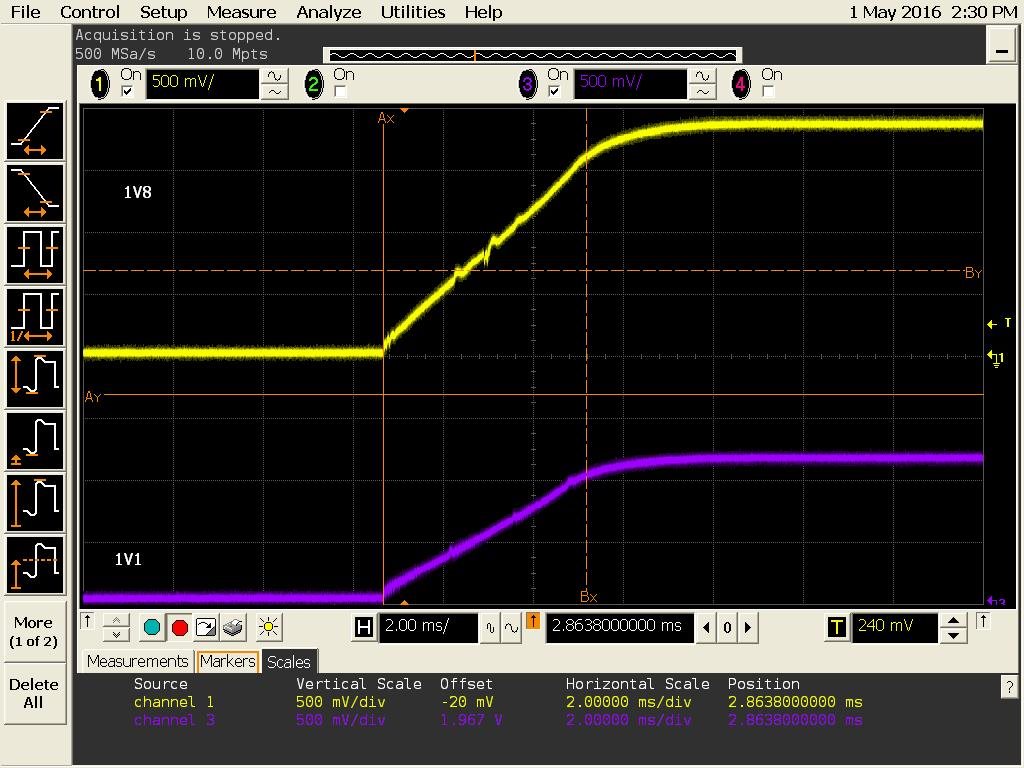
    The only thing consistent is this: Within a power-on cycle, the reset either works or it doesn’t. I.e. after powering my board, if the PHY_STATUS deasserts correctly the first time FPGA resets the PHY then PHY_STATUS deasserts consistently. If, however (most of the cases) PHY A DOES NOT deassert PHY_STATUS then it never does it within the same power-on cycle. This indicates that there is some issue with the power sequencing of the chip. I have scoped this (image 16) and it takes some 5ms for the power rails to reach valid levels. Does this matter? Occasionally, PHY B also toggles or not deasserts its PHY_STATUS signal. Mostly, 49/50, PHY B works. Mostly, 49/5. PHY A doesn't. I could try to swap the ICs on the board to see if the issue follows the chip but i think I’ve tried this way back with not much learned from it...

    My FPGA uses the following PHY reset::

    OUT_ENABLE = 1; RESETN=0; PHY_RESETN=0;

    Waits 15us

    RESETN=1; PHY_RESETN=1;

    Note that my Altera FPGA uses pull-up resistors on all I/Os when un-configured.  However, I have attached 1Kohm pull-downs to the OUT_ENABLE lines such that OUT_ENABLE will first be asserted as part of the above reset sequence. All strapping signals are correct when RESETN is deasserted and both PCLKs are stable at 250MHz.

    I need to get to the bottom of this issue so would appreciate if this somehow could be escalated. I had two board spins where this issue never showed up. I’m not sure whether it is due to the TUSB1310A parts behaving differently. Rework/replacement of PHYA on this board has not resolved the issue.

    If possible, contact me directly via the email in my account so we can communicate directly via email. I sent an email to Elias Villegas but he is out of the office until 5/9/16.

    Thanks,

    /John.

    File 4: 4 - USB_A_PHY_STATUS toggling.jpg

    File 5: 5 - USB_A_PHY_STATUS toggling [zoom-in].jpg

    File 16: 16 - 1V8 & 1V1 rails at power-on.jpg

    File 17: 17 - USB_A_ELECIDLE - noise within negative pulses.jpg

    File 19: 19 - USB_A_ELECIDLE - noise within negative pulses (zoom-in) - Ripple from PCLK.jpg

    Altera SignalTap: Altera SignalTap Trace of PHY reset.jpg

  • It appears I may have figured this issue out. It turns out that the TUSB1310A is sensitive to the slew rate of the power rails. My board uses switched regulators, which bring up the voltage gradually. It is critical that both chip reset lines is firmly held in reset while the power rails are coming up. I now have 1K pull-down resistors on the reset pins and the issue went away. The various toggling of PHY_STATUS and ELECIDLE is the TUSB1310A's way of saying that it is not happy with the strapping levels or the voltage when coming out of reset. Apparently, the chip does some initialization when the power rails are valid that is separate from what is done when the reset lines are deasserted. Making a second reset after the voltage rails have come up will not resolve this flakey behavior. The reset lines must be asserted until the power rails are good. I've seen this mentioned in passing on some technical documents but should be empathized better since extremely important. 

  • Hello,
    Thank you for all the technical contribution you have made, I will pass this information to the appropriate people.
    Regards
  • Unfortunately, with a new board spin the issue has come back. As before, one of the PHYs deasserts PHY_STATUS fine while the other one toggles with 62.5 MHz. Could you please check with the chip designers under what circumstances PHY_STATUS toggles with 1/4 of the PCLK frequency? I will email schematics and latest scope images directly to Elias.

    Thanks.
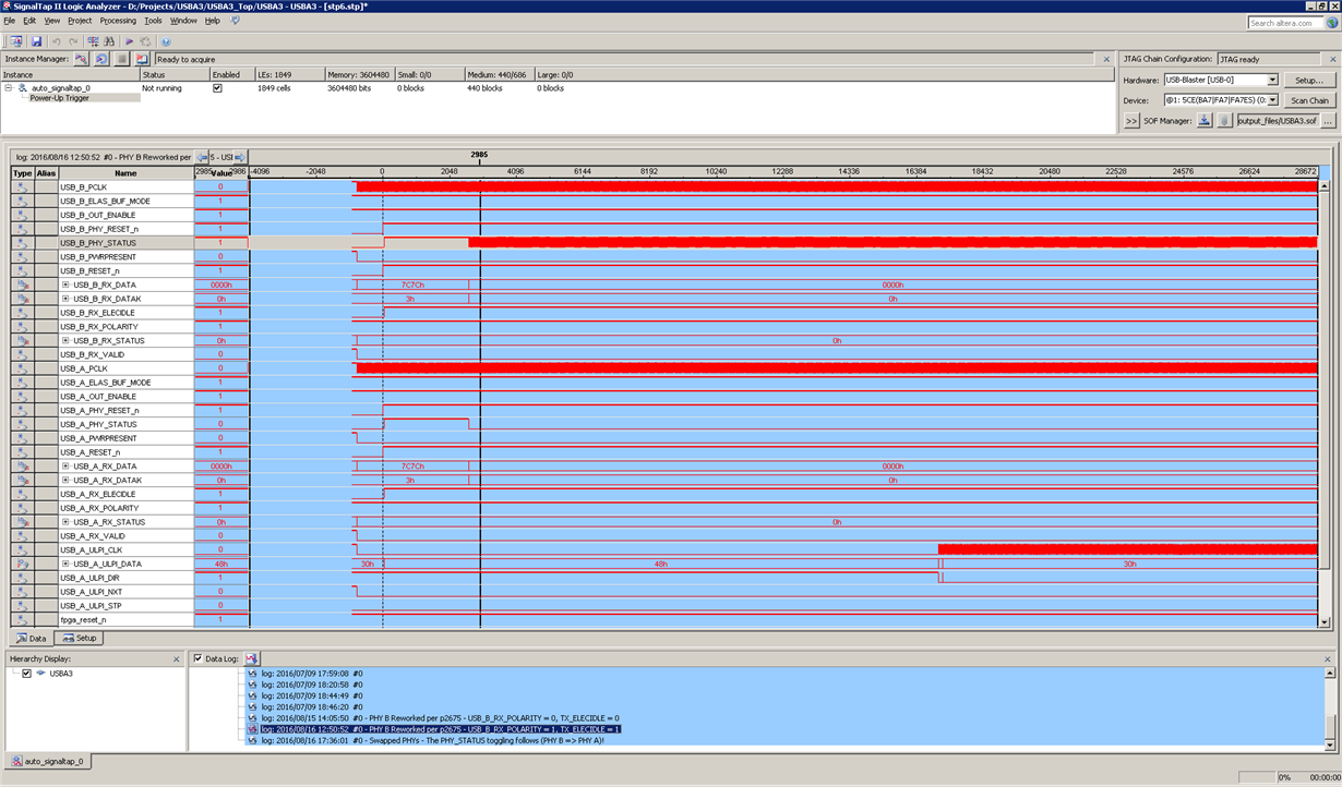
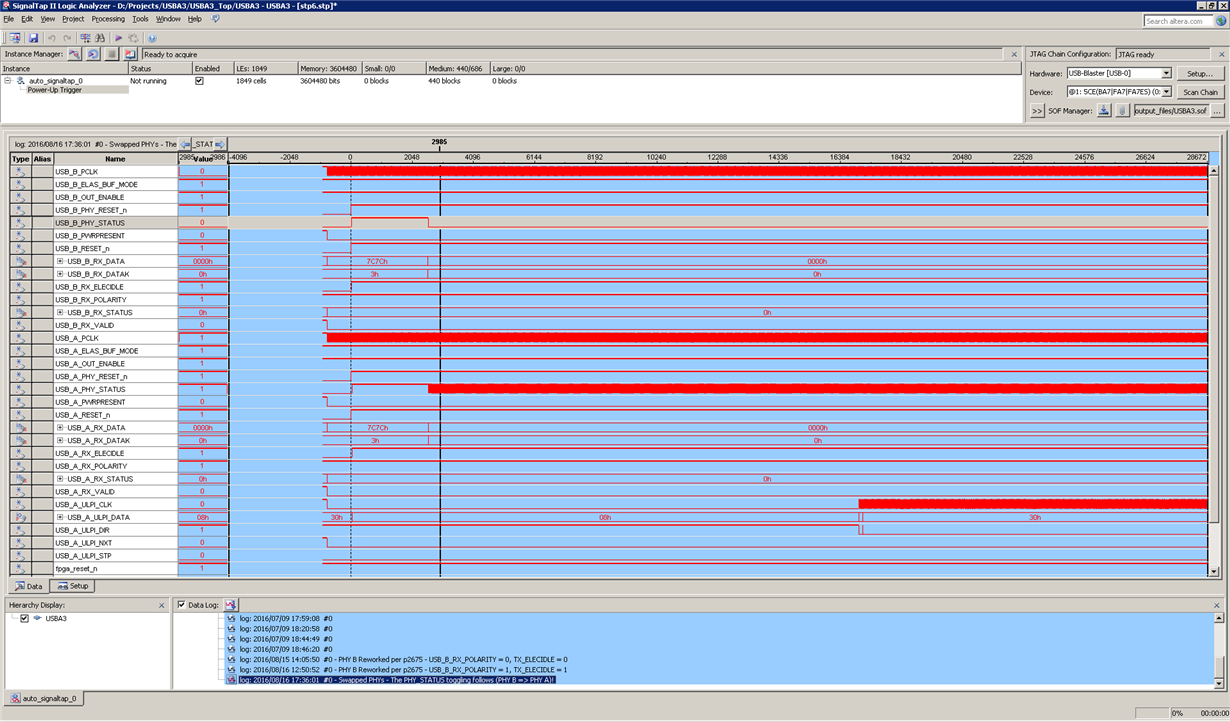
  • This issue has not yet been resolved. I have been told by your intern, who is the only one I've heard from lately, that you are working on reproducing the issue on-house. I have additional data points:

    1) It does not matter whether the PHY is on U0 or U2 power state during reset. One of the PHYs toggles PHY_STATUS after reset.

    2) It doesn't matter whether TX_ELECIDLE is 0 or 1.

    3) The issue follows the PHY when swapping the two on the board (PHY B => PHY A). See attached signaltap traces before/after the PHYs are swapped.

    (USB_B_PHY_STATUS toggles with 1/4 PCLK after reset).

    (After PHYs are physically swapped: USB_A_PHY_STATUS toggles with 1/4 PCLK after reset) - The issue follows the PHY!

  • hi, i'm karthik from chennai. i have face the same problems in TUSB1310 transciver .could u tell me the suggestion pls.
  • Hi,elias:
       Now,we are testing USB3.0 including controller,phy(TUSB1310A).The all test will be completed based-on FPGA.
    However,we are facing up much difficult ,For example we debuged signals through xilinx Vivado.


    We found out these signals value same as the table display value:


    From the debug signals RESETN is already asserted.