This thread has been locked.

If you have a related question, please click the "Ask a related question" button in the top right corner. The newly created question will be automatically linked to this question.

TLK10232 10G-KR Settings

Other Parts Discussed in Thread: TLK10232

Hello

I, is operating check the TLK10232 the following environment.
We set the register access procedures and value in reference to the documentation, but the initialization successfully both HS side / LS side
It can not be completed.
I wish any advice please.

■ Configuration
(1) LS_side
    Xilinx FPGA (XAUI 3.125MHz) => TLK10232 (4lane)
(2) HS_side
    TLK10232 (1lane 10G-KR) => Cable (LoopBack)

■ questions
(1) In use in the above configuration, whether Thank register initialization procedures and the like?
    Please tell us the necessary registers and the value is set.
    
(2) Do you want to present documents such as initialization flow?

(3) Xilinx IP side Auto Negosiation features, enable / disable a setting flow, etc.
   Do you affected?
   
■ reference materials and information
  Currently, we have implemented the register access procedures and content referring to the following article on our side
  To the configuration you want to use, please tell me the reference part of the following article.
①TLK10232_DS.pdf
②TLK10232_AN.pdf
③tlk10232_BringupProcedures_v2.pdf (page2 ~ or page10 ~)


Thank I need your help.

  • Hi,

    Could you send me your current configuration of the device, plase?

    Regards,
    Luis
  • Hello
    Luis

    Referring following forum, I have a question.
    e2e.ti.com/.../447981
    TLK10232 10G transceiver startup

    ■ Question 1
    5.Enable Link Training settings, either from within the forum described register, but has been changed set point, will Which is correct?
    Write 0x2000 to 0x1E.0096
    Write 0x0002 to 0x01.0096

    ■ Question 2
    9.LT_TRAIN_STATUS setting, either from within the forum described register, but has been changed set point, will Which is correct?
    Read 0x1E.0097
    Read 0x01.0097

    ■ Question 3
    10. The If Link Training is succesfull training completion status in, the following bits in the 0x01.0097 register, or shows the status of the following?
    Bit3 = '0'
    Bit2 = '1'
    Bit1 = '1'
    Bit0 = '1'
    We are in trouble not know the means to Bit0 = '1'.


    ■ settings
    -------------
    1. Pin configuration:
    ----------------------------------------
    Ensure ST input pin is Low
    Ensure MODE_SEL input pin is Low
    Ensure PRBSEN input pin is Low

    2. Reset Device:
    Issue a hard or soft reset (RESET_N asserted for at leaste 10us or write 1'b1 to 30.0.15)
    ----------------------------------------
    Write 0x8610 to 0x1E.0000 :Global Reset=0

    3. REFCLK input frequency and selection:
    156.25MHz / 312.5MHz (Write to 30.29.12)
    REFCLKx_P/N used (Write to 30.1.1)
    ----------------------------------------
    Write 0x0000 to 0x1E.001D :REFCLK_FREQ_SEL_0=0
    Write 0x0B00 to 0x1E.0001 :REFCLK_SW_SE=0

    4. Write 0x2000 to 7.0 (Disable Auto Negotiation)
    ----------------------------------------
    Write 0x2000 to 0x07.0000 :AN_ENABLE=0(AutoNeg_OFF)

    5. Write 0x2000 to 30.150 (Enable Link Training)
    ----------------------------------------
    Write 0x0002 to 0x01.0096 :LT_TRANINING_ENABLE=1

    6. Write 0x0000 to 0x1.9002 (MS bits) & 0x1.9003 (LS bits) Disable a 500ms time-out-counter~
    ----------------------------------------
    Write 0x0000 to 0x01.9002 :
    Write 0x0000 to 0x01.9003 :

    7. Write 0x0008 to 30.14 (Data-path Reset)
    ----------------------------------------
    Write 0x000E to 0x1E.000E :RESET(DATAPATH/TXFIFO/RXFIFO)

    8.Wait 1000ms

    9. Read 30.151 (LT_TRAIN_STATUS) to verify the status of link training process
    ----------------------------------------
    Read 0x01.0097 :"0004" or "0006"

    10. If Link Training is succesfull, then you need to read out the best settings for the pre and post cursor de-emphasis:
    -------------


    Advice I will wishes well.
  • Hello,

    Answer 1. Write 0x0002 to 0x01.0096 to enable Link Training function.
    Answer 2. Read 0x01.0097 is the correct one.
    Answer 3. According to the value that you are reading 4b'0111, it means that Link Training is in progress, till bit 2 is "0" the LT protocol is completed.

    Best Regards,
    Luis Omar Morán Serna
    High Speed Interface
    SWAT Team
  • Hello
    Lewis

    Thank you answer.
    HS side of the set does not go well.
    (LS side, it has folded communication)

    ■ settings
    1. Pin configuration
    2. Reset Device
    3. REFCLK input frequency and selection:
    4. Default HS TX setting loading and LT controls
    5. HS Serdes settings
    Write 0xA848 to 0x1E.0003
    Write 0x1500 to 0x1E.0004
    6. Issue AN_RESTART
    7.Wait 1000ms


    ■ Question 1
    5. to be carried out in the HS Serdes settings1, please tell me the setting.

    ■ Question 2
    5. setting that was carried out in the HS Serdes settings1 is, or will be immediately reflected?

    ■ Question 3
    6. When was conducted Issue AN_RESTART, does it become a HS side LOS state?
    If LOS is in an abnormal state, please tell me the possible factors.

    Advice My best wishes.
  • 0121.TLK10034_link_training_app_note (1).docHello,

    Answer 1. HS Serdes Settings is according to your system, this is because equalization settings depend of losses, cable lenght, among other characteristics of your set-up. I suppose that you are using link training process right?

    Attached you will find an app note to get an overview about the recommendations.

    Answer 2. Once you get the best settings for your system is needed to issue a data path reset, due to the new configuration takes effect.

    Write 0x8000 to 0x1E.000E (Datapath reset control).

    Best Regards,

    Luis Omar Morán Serna

    High Speed Interface

    SWAT Team

  • Hello Team

    In Start up in KR with Auto Negotiation and Link Traning
    We additional questions.

    ■ Question 1
    4. Default HS Tx settings loading and LT controls
    Register (value) and the setting order, do you think to be correct?

    ■ Question 2
    4. Default HS Tx settings loading and LT controls
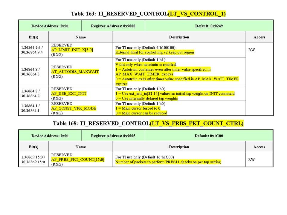
    Write 0x024D to 0x01.9000:
    Write 0x1C00 to 0x01.9005:
    In DataSheet, you can not check register.
    Please explain the settings.

    ■ Question 3
    6. value to be set in the Issue AN_RESTART is, What either of the following?
    Write 0x3200 to 0x07.0000
    Write 0x0200 to 0x07.0000

    ■ Question 4
    In 12.Clear Latched Registers, it clears the register,
    In 13.Operational Mode Status, if the value is Yomitorere, Auto Negotiation and Link Traning successfully


    In addition, the settings that are practiced, are as follows.
    ----------
    ■ settings
    1. Pin configuration:
    Ensure ST input pin is Low
    Ensure MODE_SEL input pin is Low
    Ensure PRBSEN input pin is Low

    2. Reset Device:
    Write 0x8610 to 0x1E.0000 :Global Reset=0

    3. REFCLK input frequency and selection: 156.25MHz / 312.5MHz
    Write 0x0000 to 0x1E.001D :REFCLK_FREQ_SEL_0=0
    Write 0x0B00 to 0x1E.0001 :REFCLK_SW_SE=0

    4. Default HS Tx settings loading and LT controls
    Write 0x2000 to 0x07.0000 :AN_ENABLE(Disable Auto_Negotiation)
    Write 0x0000 to 0x01.0096 :LT_TRAINING_ENABLE(Disable start-up)
    Write 0x0008 to 0x1E.000E :DATAPATH_RESET(RESET)
    Write 0x024D to 0x01.9000 :
    Write 0x0004 to 0x1E.8101 :DEFAULT_TX_TRIGGER_EN(Enable)
    Write 0x0004 to 0x1E.8100 :DEFAULT_TX_LOAD_TRIGGER_EN(Trigger loading)
    Write 0x0000 to 0x1E.8100 :DEFAULT_TX_LOAD_TRIGGER_EN(Normal)
    Write 0x0200 to 0x01.9001 :AP_SEARCH_MODE(Full region search)
    Write 0x3000 to 0x07.0000 :AN_ENABLE(Enable Auto_Negotiation)
    Write 0x0002 to 0x01.0096 :LT_TRAINING_ENABLE(Enable start-up)
    Write 0x1C00 to 0x01.9005 :

    5. HS Serdes settings
    Write 0xA848 to 0x1E.0003 :HS_SERDES_CONTROL_2 (default)
    Write 0x1500 to 0x1E.0004 :HS_SERDES_CONTROL_3 (default)


    6. Issue AN_RESTART
    Write 0x3200 to 0x07.0000 :AN_RESTART(Restart Auto Negotiation)
    AN_ENABLE(Enable Auto_Negotiation)

    7. Wait for 1000ms

    8. Poll Serdes HS_AZ_DONE_complete, HS_AGC_LOCKED locked, PLL Status locked
    Read 0x1E.000F :Expected value(xxx1_1xxx_xxxx_xx11)

    9. Poll for Auto Negotiation Complete
    Read 0x07.0001 :Expected value(xxxx_xxxx_xx1x_x1xx)

    10.Poll for Link Traning Complete
    Read 0x01.0097 :Expected value(xxxx_xxxx_xxxx_0xx1)

    11.Poll for 10GKR mode
    Read 0x07.0030 :Expected value(xxxx_xxxx_xxxx_1xxx)

    12.Clear Latched Registers
    Read 0x1E.000F :CHANNEL_STATUS_1 to clear
    Read 0x1E.0010 :HS_ERROR_COUNTER to clear
    Read 0x1E.0011 :LS_LN0_ERROR_COUNTER to clear
    Read 0x1E.0012 :LS_LN1_ERROR_COUNTER to clear
    Read 0x1E.0013 :LS_LN2_ERROR_COUNTER to clear
    Read 0x1E.0014 :LS_LN3_ERROR_COUNTER to clear
    Write 0x0030 to 0x1E.000C :LS status registers for each lane to clear (LS_lane0)
    Write 0x0130 to 0x1E.000C :LS status registers for each lane to clear (LS_lane1)
    Write 0x0230 to 0x1E.000C :LS status registers for each lane to clear (LS_lane2)
    Write 0x0330 to 0x1E.000C :LS status registers for each lane to clear (LS_lane3)
    Read 0x1E.0015 :LS_STATUS_1 to clear
    Read 0x01.0001 :PMA_STATUS_1 to clear
    Read 0x01.0008 :PMA_STATUS_2 to clear
    Read 0x03.0001 :PCS_STATUS_1 to clear
    Read 0x03.0008 :PCS_STATUS_2 to clear

    13.Operational Mode Status
    Read 0x1E.000F :CHANNEL_STATUS_1
    Read 0x1E.0010 :HS_ERROR_COUNTER
    Read 0x1E.0011 :LS_LN0_ERROR_COUNTER
    Read 0x1E.0012 :LS_LN1_ERROR_COUNTER
    Read 0x1E.0013 :LS_LN2_ERROR_COUNTER
    Read 0x1E.0014 :LS_LN3_ERROR_COUNTER
    Write 0x0030 to 0x1E.000C :LS status registers for each lane (LS_lane0)
    Write 0x0130 to 0x1E.000C :LS status registers for each lane (LS_lane1)
    Write 0x0230 to 0x1E.000C :LS status registers for each lane (LS_lane2)
    Write 0x0330 to 0x1E.000C :LS status registers for each lane (LS_lane3)
    Read 0x1E.0015 :LS_STATUS_1 to clear
    Read 0x01.0001 :PMA_STATUS_1
    Read 0x03.0001 :PCS_STATUS_1

    Best Regards
  • Hello,

    Answer 1 . As you know every system is different, hence, user needs to tune the device according to the lenght of trace/cable, losses, etc. This "tuning" could be done manually or through link training to get the best settings ofn equalization (EQPRE, ENTRACK, SWING, etc.). Attached you will find an application note that specifies the settings in Link Training Process.

    Answer 2. Attached you will find the description of both registers. This is because, these register are RESERVED, although user could be modifiy them.

    Answer 3. Write 0x3200 to 0x07.0000 is the correct one. Is important to mention that user needs to clear this register reading the AN_RESTART bit.

    Answer 4. Could you clarify your question, please?

    Best Regards,

    Luis Omar Morán Serna

    High Speed Interface

    SWAT Team

     4520.TLK10034_link_training_app_note (10).doc

  • Hello Team

    For register setting procedure at the link training, and is an additional question.

    Currently, it is material ③tlk10232_BringupProcedures_v2.pdf the (page10 ~) are creating a register access content in reference, I ★ in marked places, I have a question.


    Here, the register set the order in which they are conducted
    ↓↓
    1. Pin configuration:
    2. Reset Device:
    3. REFCLK input frequency and selection: 156.25MHz / 312.5MHz
    4. Default HS Tx settings loading and LT controls
    ①Write 0x2000 to 0x07.0000: AN_ENABLE (Disable Auto_Negotiation)
    ②Write 0x0002 to 0x01.0096: LT_TRAINING_ENABLE (Enable start-up)
    ③Write 0x0008 to 0x1E.000E: DATAPATH_RESET (RESET)

    ★ Question 5
    Here [5. HS Serdes settings] is correct to implement?
    We are, after ④Write 0x024D to 0x01.9000, I believe so that link training is started.

    <Transmitter Side>
    Write 0x0000 to 0x1E.0003
    Write 0x0000 to 0x1E.0005
    <Receiver Side>
    Write 0x0000 to 0x1E.0004

    ④Write 0x024D to 0x01.9000:

    ★ Question 6
    here. Link training begins?
    (At this point, you can see the LT_RX_STATUS = 1 of the following register)
    Read 0x01.0097: LT_RX_STATUS = 1

    ★ Question 7
    Following register ⑤ ~ ⑧ is, do you need to keep performed before link training?
    I believe in is correct to implement before ③DATAPATH_RESET.

    ⑤Wrrite 0x0004 to 0x1E.8101: DEFAULT_TX_TRIGGER_EN (Enable)
    ⑥Write 0x0004 to 0x1E.8100: DEFAULT_TX_LOAD_TRIGGER_EN (Trigger loading)
    ⑦Write 0x0000 to 0x1E.8100: DEFAULT_TX_LOAD_TRIGGER_EN (Normal)
    ⑧Write 0x0200 to 0x01.9001: AP_SEARCH_MODE (Full region search)
    ⑨Write 0x3000 to 0x07.0000: AN_ENABLE (Enable Auto_Negotiation)
    ⑩Write 0x0002 to 0x01.0096: LT_TRAINING_ENABLE (Enable start-up)

    ★ Question 8
    How do I read the link training result.
    We are, but we have carried out in accordance with ②TLK10232_AN.pdf (Section 1.2), and also read the 0x1E.9022, because the register value does not change, please tell me the procedure.

    Write 0x1000 to 0x01.9001: initializes the read-out process
    Read 0x1E.9022: conducted read 32 times, all value is FFFF.

    Best Regards.
  • Hello,

    Answer 5. First of all user have to disable Auto-negotiation and Link Training processes, till Auto- Negotiation and Link Training are enabled the process is started, even I would recommend a datapath reset after:

    o Write 16’h3000 to 7.0
    o Write 16’h0002 to 30.150
    o Write 16’h1C00 to 30.36869

    ****Write 16’h24D to 30.36864 (Datapath reset once AN & LT are enabled)

    Answer 6.  Through register LT_TRAIN_STATUS bits [2] you can monitor if the Link Training process is in progress (started) or complete.

    Answer 7. Datapath reset is needed once the configuration is done, i.e. AN & LT disabled then datapath reset. After the next configuration AN & LT & SERDES settings also user needs to perform datapath reset.

    Asnwer 8. There is a mechanism in the TLK10xxx devices to read out the results of a link training sweep.  This can be used as a quick link margin measurement, since it indicates whether or not the receiver detected errors across a large number of combinations of transmitter pre-cursor and post-cursor de-emphasis levels.

     During link training, the receiver will instruct the transmitter to iterate through different combinations of settings.  At each setting, the transmitter sends test packets and the receiver detects whether or not there are errors.  Once a point is tested, the receiver asks the transmitter to go on to the next setting.  The settings here are the pre-cursor tap and the post-cursor tap of a 3-tap FIR de-emphasis filter (this is a standard transmitter implementation, and an example of it is shown in the presentation I sent you).


    Here is the procedure to read out these test results:


    1. Write 1’b1 to 0x01.9001 bit 12.  This sets a pointer to the link training results that correspond to the minimum post-cursor de-emphasis level.  This sort of initializes the read-out process.


    1. Read register 0x01.9022.  This contains the BER data for all pre-cursor de-emphasis levels for the minimum post-cursor de-emphasis level.  The first 8 bits will always be high, but the lowest 8 bits indicate the presence (1) or absence (0) of errors during the testing at that point.


    1. If you read register 0x01.9022 again, you will get the results for all the different pre-cursor levels at the next available post-cursor level.  Each read will increment the post-cursor level, so you will need to read this register over and over (16 times) and record the values to be able to see results for every different combination.  I can help interpret these results, but basically what we are looking for is how many points have the value “0” instead of “1” – lots of points with no errors would indicate a link operating with good margin.

    Best Regards,

    Luis Omar Morán Serna

    High Speed Interface

    SWAT Team

  • Hello, team

    Thank you answer.
    I have a question in addition.

    We have a place you do not know in the register to be accessed.

    ■ Question 9 (For answer 5.)
    Link Training Start is, correct? Which following register?
    (Are you sure you want to operate successfully in either register?)
    ①Write 0x024D to 0x01.9000: Data Sheet Table8-137
    ②Write 0x024D to 0x1E.9000: answers in forum
     
    ■ Question 10 (For answer 5.)
    Link Training Enable is, correct? Which following register?
    (Are you sure you want to operate successfully in either register?)
    ①Write 0x0002 to 0x01.0096: Data Sheet Table8-68
    ②Write 0x0002 to 0x1E.0096: answers in forum

    Best Regards,
  • Hi,

    Answer 9. Write 0x024D to 0x01.9000 is the correct one.

    Answer 10. To enable Link Training you have to write 0x0002 to 0x01.0096.

    As you know for both registers you use Device Address: 0x01

    I hope this helps,

    Best Regards,

    Luis Omar Morán Serna

    High Speed Interface

    SWAT Team