This thread has been locked.

If you have a related question, please click the "Ask a related question" button in the top right corner. The newly created question will be automatically linked to this question.

[TMDS361B] IC2 pin's behavior when power is not applied

Other Parts Discussed in Thread: TMDS361B

Hi team,

My customer would like to know I2C pin's behavior of TMDS361B(I mean S1/SCL and S2/SDA) when its power is not applied. In their circuit, one of power line connected EEPROM wakes up first to initialize a MCU, so the voltage of the line will be applyded to  S1/SCL and S2/SDA pin's prior to its power supply.

Their questions is as below.

Do the S1/SCL and S2/SDA pins behave as Hi-Z under no power supply condition?

If it's "NO", we plan to recommend them switch devices to cut off current leakage. 

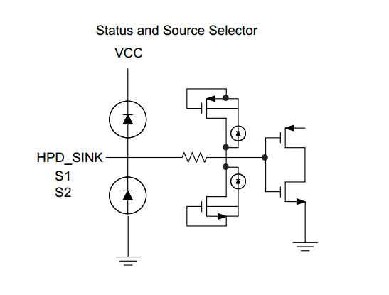
As far as I looked into the datasheet, there are a block diagram which indicates around circuit of the Pins as below. And it looks there are some diodes between the pins and Vcc. But the additional swithch it not desirable for them, so let me ask on this just in case.  

Regards,

Takashi Onawa

  • Hi Takashi,


    I just tested in the lab asserting 3.3V to S1/S2 pins without any power supply on TMDS361B.

    I couldn't see any leakage current from TMDS361B pins at least not around uA,

    I powered up TMDS361B without HDMI connection I could see around it consumes 24mA, agains asserting 3.3V on S1/S2 pins didn't make a difference.

    Regards

  • Hi Moises-san,

    Thanks for testing. But I think we can not say the pins behave as Hi-Z only the leakage.

    Could you tell me the detail of your experimental setup?

    If Vcc pin was floating on the setup, you might see the leackage between VCC and GND, not the leackage between Vcc and S1/S2. So let me check  Vcc voltage level when asserting 3.3V at S1/S2 without any power supply and whether the Vcc was terminated to GND with a resister in your validation or not.

    Eventually, Can TI  no switchs are needed in this use case? 

    Regards,

    Takashi Onawa

  • Hi Takashi,

    The experimental setup is as follows:

    TMDS361B EVM

    3.3V lab power supply

    1 voltage meter

    1 current meter

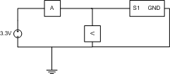
    Setup looks something like this:

    The EVM has other components from Vcc to GND like diodes and resistors, if there is any leakage the current injected to S1/S2 pin would be greater than 0.01uA(small value because of current meter offset?).

    If you suggest other testing I can try it.

    In our group we don't have general purpose MOS switches.

    Regards

  • Hi Moises-san,

    Could you also check Vcc voltage level assering 3.3V at S1/S2 at least?
    If there are current pass between Vcc and S1/S2, you might see some voltage at Vcc.

    If possible, I want to know all pin's voltage level when asserting 3.3V at S1/S2 though..

    Regards,

    Takashi Onawa

  • Hi Moises-san,

    May I ask whther you can try the test above?
    I need to explain our status to my customer.

    Regards,
    Takashi Onawa
  • Hi Takashi-san,

    I continued with testing on TMDS361BEVM, If I apply 3.3V on S1/S2 there is no voltage on Vcc, however I see voltage on S2/S1.

    I will contact char team to see if the can tests a different board that could exhibit a voltage on Vcc.

    Regards

  • Hi Moises-san,

    Thanks for testing again and it sounds the S1/S2 pin behaves Hi-z with no supply condition.
    I'm wandering if I can get any update on the confirmation to char team though, Can I?

    Regards,
    Takashi Onawa
  • Hi Takashi-san,

    I received confirmation control pins are not fail safe, so, there should be a leakage on S1/S2 I'm not able to measure because of EVM components.
    Char team is looking for a board to do this test, design team could run some simulations but it take around 3 weeks.

    Regards
  • Hi Moises-san,

    Thanks for confirming. I will recommend them to put FET there.
    I would ask you to do your suggestions above if they disired re-check test and the simuration.

    Regards,
    Takashi Onawa