This thread has been locked.

If you have a related question, please click the "Ask a related question" button in the top right corner. The newly created question will be automatically linked to this question.

SN75DP130: Sometimes register value is changed

Part Number: SN75DP130

Hi.

My customer using SN75DP130.

But sometimes 0x01 register value is changed.

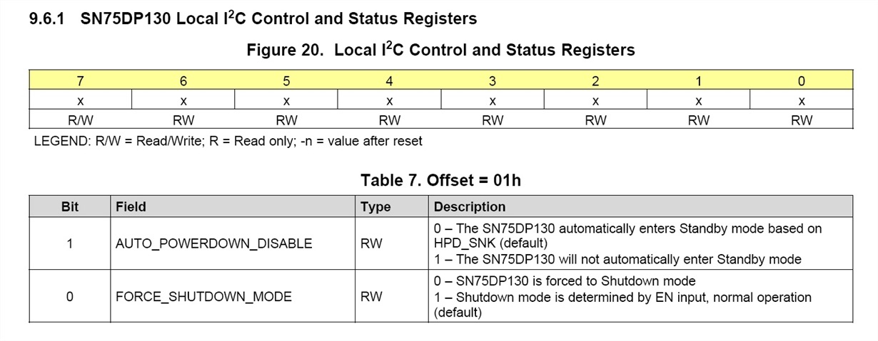
This register is about Shutdown Mode in Local I2C Control and Status Registers.

Default value is 0x01.

But sometimes this chip is shutdown, So when they read this register, it is changed to 0x48 or 0x64 or 0x68 or 0x6C.

The bit-0 is 0, so chip is shutdown.

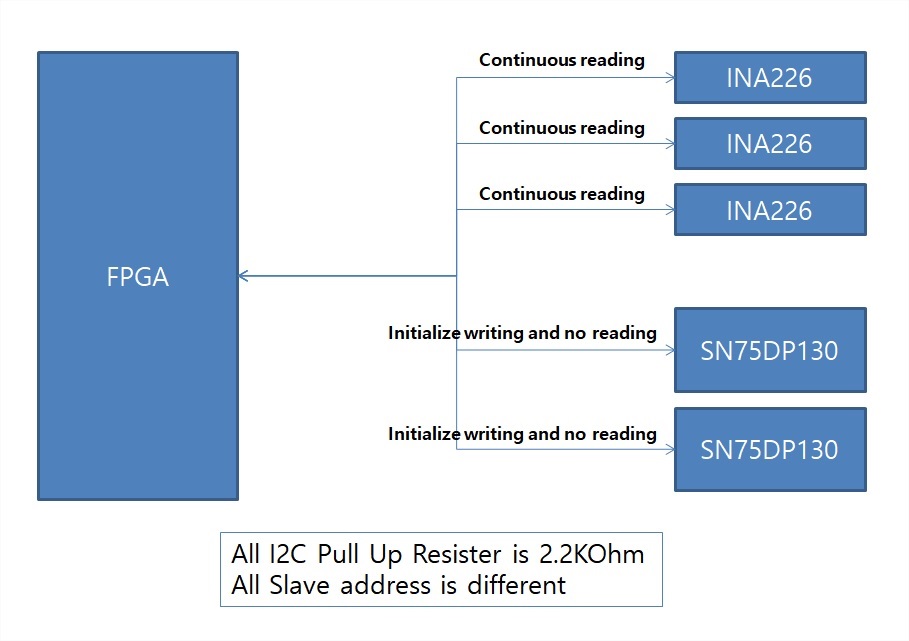
The block is below image.

And when this situation is occurred, There is no writing behavior to SN75DP130.

Please let me know how to fix this.

Thanks.

  • Hello Jung

    We are working on it. Thanks for your patient.

    Regards
    Francisco
  • Hello SS

    Can you describe in more detail in what kind of situation they have this behavior? Can you share more information regarding the application, like the schematic? When you said "But sometimes this chip is shutdown", they forced the device to be in shutdown mode?

    Regards
    Francisco
  • Hi Francisco.

    I attach the schematic below.

    1) No write and read action into SN75DP130DS during operation except first initialization.

    2) After operation 24~48hours, suddenly SN75DP130DS is shutdown.

    3) Read "Local I2C Control and status registers", 01h register is 0x48 or 0x64 or 0x68 or 0x6c.

    4) These register is "forced shutdown mode" because Bit 0 = 0

    Why this abnormal operation is occurred?

    And I tried writing 0x48 or 0x64 or 0x68 or 0x6c into 01h register, but 0x00 is written.

    According this 01h register's vaild bit is BIT 0 and BIT 1.

    But atfer suddenly shutdown, 01h register value is 0x48 or 0x64 or 0x68 or 0x6c and this value's BIT 0 is 0, Forced shutdown mode.

    Any read and write action is not excuted, but register value is changed.

    Please let me know about this symptom.

    Thanks.

  • Hello SS

    I am working on the review. Thanks for your patient.

    Regards
    Francisco
  • Hello SS

    I would like to confirm if you follow the power-up sequence? We recommend to start with .2uF at RST pin and tweak as needed. This one can affect the behavior.
    I would like to confirm the work mode that you are using. If you are using the DP++ the pull-up/down resitors on AUX channel must be on SNK side and the capacitors on SRC side.
    The local I2C lines, have to have 2k pull-up resistors.

    Regards
    Francisco

  • Hi Francisco

    I already check power up sequence and RSTN's PU resistor.

    I think power up sequence and RSTN's PU resistor is no problem.

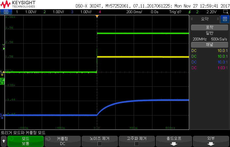
    Please refer below waveform.

    Green : VCC (3.3V) - actually 3.3V

    Yellow : VDDD

    Green : PSTN (RESET)

    They using DP Only Configuration with AUX Pass Through mode.

    If DP Only mode, AUX_SNK/SRC PU,PD,CAP is not related? 

    Please refer below schematic.

    Francisco.

    The issue is about wrong register value situation.

    We try to write 48 or 64 etc in 01h but only be written 00 value in 01h.

    But when shutdown issue is occurred, the 01h value is 48 or 64 or 68 etc.

    Is this possible? and they want to know why.   

    Thanks

  • Hello SS

    We have to be sure about the schematic because if you have a wrong connection, the device can works wrong for this reason. We have to start with this part to continue debugging.
    According to your diagram, it has a wrong connection, In case of the AUX_sink, this lane has to have a 100k pull-up and pull-down for each line (AUXSNK - to up and AUXSNK + pulldown). The CTL lines have to be pulled-up because are I2C lines (we recommend using 10 k). In case of AUXSRC lines, these lines have to have 100 n AC-coupling capacitors connected to the source.
    For the power supply, we recommend using one 100nF cap on each power pin one bulky cap close to DP130.

    On the other hand, it doesn't make me sense why the customer wants to write on these bits, these bits are reserved for users.

    Please, do these changes and let me know your feedback.


    Regards
    Francisco
  • SS

    I also took a look at your timing signals, and they look ok but it's a long time for RSTN. That's why we recommend using a smaller capacitor and you can tweak as needed. If this time is very long, sometimes this device present weird behavior. Then, please change this capacitor.

    Regards
    Francisco
  • Hi Francisco.

    Your answer about AUXSRC and AUXSNK line is about source side re-driver.
    My customer is sink side re-driver.
    According SLLA349, Aux line is different from datasheet(source side).
    I ask another questions.
    Please refer below link and let me know.
    e2e.ti.com/.../2409761
  • Hello SS

    I've answered this question on the other post e2e.ti.com/.../2409761

    Regards
    Francisco