This thread has been locked.

If you have a related question, please click the "Ask a related question" button in the top right corner. The newly created question will be automatically linked to this question.

SN75DP126: Firmware programming issue...

Part Number: SN75DP126

Dear Sir,

Customer met some question while they implement firmware into their BIOS.

As customer feedback, there is no problem to write AEQ registers, but after write data into DPCD register and read back, all they can get is "0".

Is there any method to check if data were be written in registers?

Below are the data they write.

Thanks.

Output Voltage Level (Bit 10):

LANE0 --> DPCD 000103h  value 10

LANE1 --> DPCD 000104h  value 10

LANE2 --> DPCD 000105h  value 10

LANE3 --> DPCD 000106h  value 10


Pre-Emphasis Level (Bit 32):

LANE0 --> DPCD 000103h  value 00

LANE1 --> DPCD 000104h  value 00

LANE2 --> DPCD 000105h  value 00

LANE3 --> DPCD 000106h  value 00


AEQ Setting:

LANE0 --> AEQ 05h(BIT 6、4)  value 100

LANE1 --> AEQ 05h(BIT 2、0)  value 100

LANE2 --> AEQ 06h(BIT 6、4)  value 100

LANE3 --> AEQ 06h(BIT 2、0)  value 100

  • Peter,

    For Pre-Emphasis Level they should be writing to Bits 4:3 then reading bits 3:2. What values do they read for Output Voltage Level (Bit 1、0) after a write, all 0? Are there any NACK seen on the I2C bus when reading or writing?
  • Dear Sir,

    As customer feedback, they had use LA to capture signal and saw ACK signal existing.

    They use SMBUS protocol to write DPCD but it seems fail to write into register, and I2C_EN is logic "1" for sure.

    Besides, they mentioned what is the format for the DPCD write and read? WORD or BYTE? 

  • The format should be BYTE. Is the customer, for Pre-Emphasis Level, writing to Bits 4:3?

  • Malik Barton57 said:

    The format should be BYTE. Is the customer, for Pre-Emphasis Level, writing to Bits 4:3?

    Hi Sir,

    As data provided by customer, they writing to Bits 3:2


    Output Voltage Level (Bit 10):

    LANE0 --> DPCD 000103h  value 10

    LANE1 --> DPCD 000104h  value 10

    LANE2 --> DPCD 000105h  value 10

    LANE3 --> DPCD 000106h  value 10


    Pre-Emphasis Level (Bit 32):

    LANE0 --> DPCD 000103h  value 00

    LANE1 --> DPCD 000104h  value 00

    LANE2 --> DPCD 000105h  value 00

    LANE3 --> DPCD 000106h  value 00

  • Peter,

    Please try writing to Bits 4:3 as per datasheet Table 5. DPCD Registers Utilized by the SN75DP126 AUX Monitor. Bits 3:2 are for reading the values. 


  • Peter,

    Also what address are they using to read SN75DP126 when I2C_CTL_EN is high?
  • Thanks.
    I will discuss with customer try to write Bits 4:3 and see if it is OK.
  • Dear Sir,

    Another question is, if customer want to set "Voltage Swing Level 2" and "Pre-emphasis level 0 ", how should they do?
    What registers should they set? 1Fh or 00103h ?
  • Peter,

    The writes to the DPCD space occur through registers 1Ch - 1Dh (address) and 1Fh (data) in local I2C space. See example below for writing "Voltage Swing Level 2" and "Pre-emphasis level 0 " to lane 0.

    ======Program VOD L2 and Pre-Emphasis L0 for Lane 0=====

    ======DPCD 00103h =====

    <i2c_write addr="0x2D" count="1" radix="16">1C 00 />

    <i2c_write addr="0x2D" count="1" radix="16">1D 01 />

    <i2c_write addr="0x2D" count="1" radix="16">1E 03 />

    <i2c_write addr="0x2D" count="1" radix="16">1F 02 />

    ======Read DPCD 00103h, Lane0 =====

    <i2c_write addr="0x2D" count="1" radix="16">1C 00 />

    <i2c_write addr="0x2D" count="1" radix="16">1D 01 />

    <i2c_write addr="0x2D" count="1" radix="16">1E 03 />

    <i2c_write addr="0x2D" count="0" radix="16">1F />

    <i2c_read addr="0x2D" count="1" radix="16">1F /> <--- Expect value of 02 to be return*

    Check Table 5. DPCD Registers Utilized by the SN75DP126 AUX Monitor to confirm read values 

  • Dear Sir,

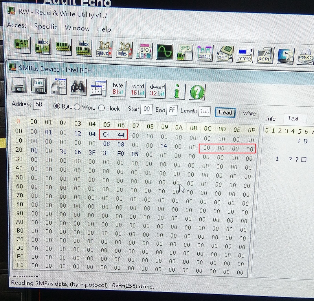
    Below is the snapshot of customer tooling that shown what they writing are all "00", but the I2C_EN was written indeed.

    customer only set DP126 value with red mark address, and 05h and 06h value keep their setting, but 1Ch,1Dh,1Eh, and 1Fh always keep "00".

    It is very strange why 05h and 06h can be set and keep value but the others are not?


    I also attached customer code that only for DP126 setting section in their BIOS.

    Can you help to check if there is anything wrong with it?

    Thanks.

    code.txt
    EFI_STATUS Init_Gen
    (
        IN EFI_PEI_SERVICES             **PeiServices,
        IN EFI_PEI_NOTIFY_DESCRIPTOR    *NotifyDescriptor,
        IN VOID                         *NullPpi
    )
    {
        EFI_STATUS        Status;
        EFI_PEI_SMBUS_PPI    *SmBus;
        EFI_SMBUS_DEVICE_ADDRESS    Address;
        UINT8        Value;
        UINTN        Len = 1;
    
        Address.SmbusDeviceAddress = 0x5A >> 1;
    
        Status = (*PeiServices)->LocatePpi( PeiServices,
                                                    &gPeiSmBusPpiGuid,
                                                    0,
                                                    NULL,
                                                    &SmBus );
        ASSERT_PEI_ERROR( PeiServices, Status);
    
        Value =  0x80;
        SmBus->Execute( PeiServices, SmBus, Address, 0x05, EfiSmbusWriteByte, 0, &Len, &Value);
    
        Value =  0xC4;
        SmBus->Execute( PeiServices, SmBus, Address, 0x05, EfiSmbusWriteByte, 0, &Len, &Value);
    
        Value =  0x44;
        SmBus->Execute( PeiServices, SmBus, Address, 0x06, EfiSmbusWriteByte, 0, &Len, &Value);
    
        Value =  0x00;
        SmBus->Execute( PeiServices, SmBus, Address, 0x1C, EfiSmbusWriteByte, 0, &Len, &Value);
    
        Value =  0x01;
        SmBus->Execute( PeiServices, SmBus, Address, 0x1D, EfiSmbusWriteByte, 0, &Len, &Value);
    
        Value =  0x03;
        SmBus->Execute( PeiServices, SmBus, Address, 0x1E, EfiSmbusWriteByte, 0, &Len, &Value);
    
        Value =  0x02;
        SmBus->Execute( PeiServices, SmBus, Address, 0x1F, EfiSmbusWriteByte, 0, &Len, &Value);
    
        Value =  0x00;
        SmBus->Execute( PeiServices, SmBus, Address, 0x1C, EfiSmbusWriteByte, 0, &Len, &Value);
    
        Value =  0x01;
        SmBus->Execute( PeiServices, SmBus, Address, 0x1D, EfiSmbusWriteByte, 0, &Len, &Value);
    
        Value =  0x04;
        SmBus->Execute( PeiServices, SmBus, Address, 0x1E, EfiSmbusWriteByte, 0, &Len, &Value);
    
        Value =  0x02;
        SmBus->Execute( PeiServices, SmBus, Address, 0x1F, EfiSmbusWriteByte, 0, &Len, &Value);
    
        Value =  0x00;
        SmBus->Execute( PeiServices, SmBus, Address, 0x1C, EfiSmbusWriteByte, 0, &Len, &Value);
    
        Value =  0x01;
        SmBus->Execute( PeiServices, SmBus, Address, 0x1D, EfiSmbusWriteByte, 0, &Len, &Value);
    
        Value =  0x05;
        SmBus->Execute( PeiServices, SmBus, Address, 0x1E, EfiSmbusWriteByte, 0, &Len, &Value);
    
        Value =  0x02;
        SmBus->Execute( PeiServices, SmBus, Address, 0x1F, EfiSmbusWriteByte, 0, &Len, &Value);
    
        Value =  0x00;
        SmBus->Execute( PeiServices, SmBus, Address, 0x1C, EfiSmbusWriteByte, 0, &Len, &Value);
    
        Value =  0x01;
        SmBus->Execute( PeiServices, SmBus, Address, 0x1D, EfiSmbusWriteByte, 0, &Len, &Value);
    
        Value =  0x06;
        SmBus->Execute( PeiServices, SmBus, Address, 0x1E, EfiSmbusWriteByte, 0, &Len, &Value);
    
        Value =  0x02;
        SmBus->Execute( PeiServices, SmBus, Address, 0x1F, EfiSmbusWriteByte, 0, &Len, &Value);
    
        PEI_TRACE((TRACE_ALWAYS, PeiServices, "Program CK505 end.\n"));
    
        return EFI_SUCCESS;
    

  • Peter,

    I have reviewed the posted code an could not find any issues. Could you try reading out of 0Fh for the DCPD registers that were written? Please use the example I posted as a guide on how to do this, this is how you read the actual DCPD registers.
  • Malik Barton57 said:
    Peter,

    I have reviewed the posted code an could not find any issues. Could you try reading out of 0Fh for the DCPD registers that were written? Please use the example I posted as a guide on how to do this, this is how you read the actual DCPD registers.

    Dear Sir,

    Can you figure out what register is for 0Fh?

    Sorry that I am not software FAE.

    Thanks.

  • Peter,

    Register 0Fh holds the data that is being written or being read to/from the DCPD registers. When you want to read the DCPD registers you write the DCPD address to registers 1Ch- 1Eh and the read data at the chosen DPCD register address from 1Fh. 

    SN65DP130 has a similar function for read/write to DCPD registers. Below is a brief explanation of SN65DP126/SN65DP130 registers 1Ch-1Fh.

    Source for above image: www.ti.com/.../slla349.pdf