


I am trying to interface the LMP 91000 evaluation board with a Microchip 16F877 microcontoller.
I have tried the built-in I2C functions but can not get an Ack for the 9th bit. Using a scope the SDA line stays around 1.8V for the Ack bit.
I have also tried programming the MENB, SDA and SCL directly, here the SDA stays low when I convert the PIN from output to input until the SCL line drops for the 9th bit then the SDA line climbs anywhere from 1 V to 5V for around 9 micro-seconds. (see scope picture for fixed unti addr 1001000+0 for a write)
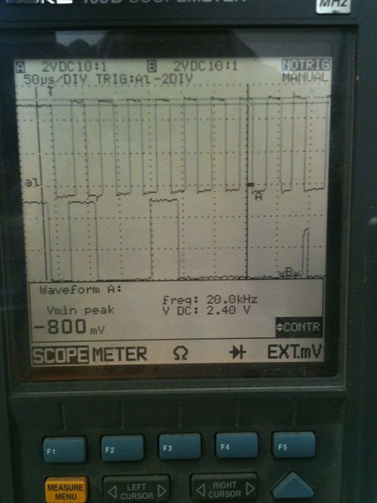
Is this an Ack or Nack response? From the timings section the ACK is valid from the drop of the SCL line for a max of 3.45 us (does not specifiy a min time).

