This thread has been locked.

If you have a related question, please click the "Ask a related question" button in the top right corner. The newly created question will be automatically linked to this question.

ULN2803 voltage level clarification

Hello everyone,

I have to drive four 5v loads (located at different position) using single micro-controller pin. My circuit board behaves exactly same we want it to be. However we are bit of confused with voltage level.

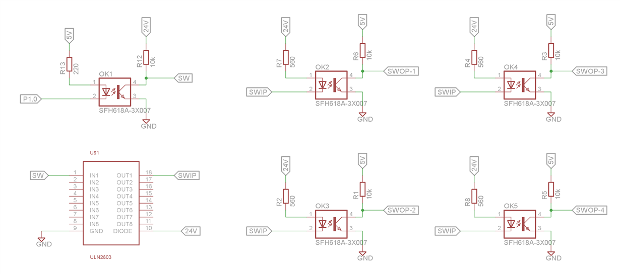
P1.0 is micro-controller pin that drives four loads connected with SWOP-1, SWOP-2, SWOP-3, SWOP-4. All four loads are working fine as per P1.0. The doubt we have is with SW. Voltage level measuring at SW is 6.23v when P1.0 is 0v but I think it should be 24v. Is 6.23v okay or it has to be 24v? When we disconnect SW from ULN2803 it measures 24v but when we connect it to IN1 of ULN it becomes 6.23v.

Awaiting response from community members.

Thank you,

Niral

  • Niral,

    Please note the internal structure of the ULN2803 (from the datasheet):

    You are setting up a voltage divider so that the input has a lower voltage than 24 V. I would expect it to be higher than 6V, but that is why you are reading a lower voltage.

    That voltage is enough to trigger the input if necessary, so it should still work, but it is kind of a strange setup.

    Is there a reason you are using an optoisolator for the switch? You could probably drive the input of the ULN2803 directly from the MCU assuming it can source a couple of mA, because 5V is enough to control the ULN2803.

    Best,
    Michael

  • Hello Michael,

    There are four buzzers connected to SWOP-1 to SWOP-2 which are located at around 180 feet away from our circuit board. Before using optocoupler buzzers were turning on automatically so we put optocoupler but problem is still there. I am suspect it is due to long distance. We are using 24v/5Amp SMPS to power up entire system. It would be great if you or someone can suggest remedy to this problem.

    Is there any application note or design guideline available from TI for long distance input ant output?

    Thanks,

    Niral

  • Niral,

    A few scattered thoughts:
    Can your MCU sink up to 22mA? Based on your 220 Ohm resistor, thats what it will need to be able to do.

    Only when your MCU pin is HIGH, the SW will then go HIGH (albeit based on a voltage divider, but it should be good enough), once the SW is HI, then the SWIP will go LOW, pulling the SWOP LOW, which will turn off the buzzer by pulling its input to GND.
    In short, MCU HIGH turns off the buzzer, is that your intention?

    Also, I am not exactly aware of the conditions that need to exist to turn the buzzer on, but is there a low output voltage that needs to be met to turn off the buzzer. Because of the voltage drop of the transistor, some voltage will still exist at the SWOP pins even when the intention is to pull them low.

    First I would suggest getting this system working at a short distance to make sure that it is behaving the way you want it to. Once you get that working then a longer distance could be done, but is certainly going to have its complications (180 feet is a long transmission line). 

    Best,
    Michael

  • Michael J Schultis said:

    Can your MCU sink up to 22mA? Based on your 220 Ohm resistor, thats what it will need to be able to do.

    It was working with 22mA however I have replaced 220 Ohm with 560 Ohm (8mA). Issue is still not solved.

    Michael J Schultis said:


    Only when your MCU pin is HIGH, the SW will then go HIGH (albeit based on a voltage divider, but it should be good enough), once the SW is HI, then the SWIP will go LOW, pulling the SWOP LOW, which will turn off the buzzer by pulling its input to GND.
    In short, MCU HIGH turns off the buzzer, is that your intention?

    When MCU pin is HIGH, SW will go HIGH so SWIP will go LOW which makes SWOP-n LOW so buzzer will get turn on. Positive terminal of buzzer is directly connected to positive.

    Michael J Schultis said:

    Also, I am not exactly aware of the conditions that need to exist to turn the buzzer on, but is there a low output voltage that needs to be met to turn off the buzzer. Because of the voltage drop of the transistor, some voltage will still exist at the SWOP pins even when the intention is to pull them low.


    We have photo detector connected with MCU pin as input, We have continuous light light source on it so when any objects come in between photo detector informs this to MCU and MCU will turn the buzzer on.

    Michael J Schultis said:

    First I would suggest getting this system working at a short distance to make sure that it is behaving the way you want it to. Once you get that working then a longer distance could be done, but is certainly going to have its complications (180 feet is a long transmission line). 

    I have tested system at a short distance and it is working completely fine.

    Now I'm pretty much sure that it is because of long distance. As use of type of wire is not in our end so we can not recommend our customers to use twisted pair cable. You mentioned about line driver, is it be able to solve this?

    Thanks,

    Niral

  • Niral,

    My suggestion would be to decrease the 560 ohm resistor on the optocoupler to increase the drive.

    Best,
    Michael