This thread has been locked.

If you have a related question, please click the "Ask a related question" button in the top right corner. The newly created question will be automatically linked to this question.

Interface HDMI to controler with TPD12S016

Other Parts Discussed in Thread: TCA9406, TPD12S016

HI,

I fond this IC (TPS12S016) and I want to use it, but I'm not shore if I can.

Here is my application:

For HDMI SDA and HDMI SCl I'm using TCA9406 input site 1.8V and output site 5V (HDMI)

Question 1: on thic chpi si conected on the hdmi site on SDA and SCL line pull-up resistor(2.2kohm) in series with shotkey diode(PMEG3020EH), what is the meaning?

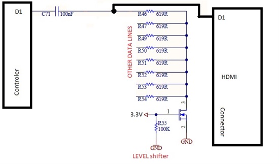
For Data0+,Data0-,Data1+,Data1-,Data2+,Data2-,clk+,clk- Signal level shifter are used resistors and one NMOS like on attached picture.

Question 2: How is this configuration working and does the TPD12S016 does the same?(level on the controler side not shore maybe 1.8V)?

Question 3: Does the IC TPD12S016 has an current limit switch like this

http://diodes.com/datasheets/AP2331.pdf

and ESD EMI protection like  this 

http://www.littelfuse.com/~/media/electronics/datasheets/tvs_diode_arrays/littelfuse_tvs_diode_array_sp3010_datasheet.pdf.pdf

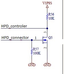
and HOT plug detection to replace this:

Question 4: DO I have to use series capacitor 100nF for data lines when using the TPD12S016?

Best Regards.

  • Hello,

    My answers:

    Q1: I looked through the datasheet and the only capacitors I see associated with the pull-up resistor nets are the bypass capacitors on the voltage sources. The purpose of these is to stabilize the voltage if any instantaneous current is needed such as when the level shifters are switching.

    Q2. The level shifters shown are MOS-FET VLTs that do not provide high impedance buffering. When the FET is on the line goes to GND and when off the pull up resistor pulls up the voltage to, say, 5V. This way the voltage Range on the input (at the gate of FET) can be 0 - 3.3V and the output can be 0-5V.

    The TPD12S016 does not use this type of VLT. They are buffered CMOS Logic-Level Translators that have a high input impedance.

    Q3. Yes & Yes.

    Q4. I have not seen the HDMI spec calling for blocking capacitors on the data lines. However, if it does they should be placed between TPD12S016 and the HDMI transmitter.

    Regards,

  • Hi Guy,

    Thanks for the answers.

    The datasheet from the uP tells to add AC coupling capacitor . Maybe You know some app note for the theory using this?

    And about the TPD12S016, I see that the I2C lines have level shifting but the data lines does not have it or am I missing it in the datasheet? 

    Does the HPD on TPD12S016 has inverted logic or not? I need when is there 5V on connector it should be 0V on the uP. Is there a similar IC with that?

    Do I have to use level shifting, and  which IC should I use?

    Best regards.

  • The only capacitors I see in the uP data sheet are coupling capacitors on the power pins (to provide instantaneous current and dampen power supply noise) and an effective 15 pF capacitor showing the load capacitance, which is not a recommended capacitor but represents the load.

    You are correct, there is no level shifting of the data lines.

    HPD on 12S016 does not have inverted logic. You could use an inverter if you wish to invert the signal.

    You don't have to use level shifting if your logic level meets the HDMI spec, but most logic levels are lower than 5V  required for DDC (SCL, SDA) so we provide the buffering VLTs for that.

    Regards,