This thread has been locked.

If you have a related question, please click the "Ask a related question" button in the top right corner. The newly created question will be automatically linked to this question.

Pulling-up resistors with TXS0102

Other Parts Discussed in Thread: TXS0102

Hi,

Ordinarily, many I2C protocols require pulling-up resistors with typical value of 2.2K.


However, in TXS0102 there are internal pulling-up resistors of 10K on both A and B side. Does this mean external pulling up resistors with value like 2.2K are no longer needed?

Or, if I am keeping both the original 2.2K and 10K of TXS0102, then in the case when either A or B side of the I2C is being pulled low by turning on the open-drain transistor, the equivalent pulling-up resistor would have value:

R = 2.2K ∥10K ∥10K = 1.53K.

Is this calculation correct? Would 1.53K pulling-up resistor work?


Philips


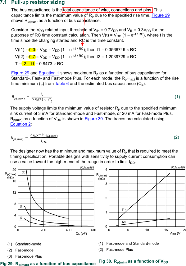
According to UM10204 I2C-bus specification and user manual, there are requirements on RP(min) and RP(min) to meet protocol timing and driving capability specification. So should the actual value be calculated accordingly with wire, connection and pins being taken into account?


Tim Baker

  • Hi Tim,

    Your calculation of equivalent pull-up resistance is correct, it will be the parallel resistance of the external pull-up and the internal pull-up.

    Because the TXS0102 has 'one-shot' edge rate acceleration circuitry, you do not need to follow the Rp(min) requirement as closely. This is because not only is the RC driving the LOW to HIGH transition- the TXS0102 'one-shot' is helping too.

    Unless you expect to be operating at a high speed (>400kHz), and with heavy loading capacitance (>100pF,) the 10kOhm internal pull-up resistance, along with the 'one-shot' circuity will be enough.

  • Hattie,

    First,

    In addition to TXS0102, the I2C bus is also communicating devices directly, not via TXS0102. For those devices, the ordinary pullup resistor is 2.2K. 

    Do you mean that with the addition of TXS0102 which has 10K ressitor on both sides, the 2.2 pullup resistor in the original circuit can be removed?


    Second,

    I don't really understand what the "one-shot" circuit is, excepting knowing that it turns T1/T2 for around 30ns during a rising edge to lower the impedance temporarily. I googled it and found no truly pertinent result. What is its architecture and construction? And could you refer me to some reference materials?


    Tim

  • Yes, you can remove the 2k2 pull-ups in the original circuit if you always have the TXS0102 enabled. It's pull-up resistors are on the bus as long as the TXS0102 is enabled.


    http://www.ti.com/lit/an/scea044/scea044.pdf

    The above application note has a description of the one shot circuits with illustrations.

  • Hattie,

    Wouldn't 10K (or 10K∥10K = 5K) too large, since the original resistors are only 2.2K?


    Tim

  • Because the TXS0102 has circuitry that temporarily reduces the driver impedance during the rising edge of signals, the pull-up resistance does not have to be so small.

  • Hattie,

    Got it, thanks.


    Tim