This thread has been locked.

If you have a related question, please click the "Ask a related question" button in the top right corner. The newly created question will be automatically linked to this question.

TCA8418 configuring/reading GPI Interrupts?

Other Parts Discussed in Thread: TCA8418, TCA8418E

I'm having problems with configuring/using interrupts on TCA8418 in GPI Mode. Polling the INT register results in alternating interrupt and no-interrupt signals regardless of if a change in pin state has actually occurred. I am attempting to monitor 6 lines attached to the GPIO of the TCA8418 via a USB-MSSP(I2C) adapter and a custom PC application. I have established communications between the PC and the TCA8418 successfully. I am able to monitor the inputs successfully via polling, but am having issues configuring the interrupt properly as to be able to poll the interrupt register to determine if a read is necessary.

Here is the procedure I am currently following:

Since the lines I'm monitoring are on GPI, I am sending a 0x02 to the CFG register (0x01). This should enable interrupts coming from changes of state on the GPI pins.

I am then writing a 0x3F to the GPIO_INT_EN1 register (0x1A). This should enable interrupts only on the specific pins I want to monitor (GPI[5]-GPI[0]/ROW[5]-ROW[0]).

The lines I am monitoring are low-active, so I want an INT to trigger on transitions from HIGH to LOW. If I'm not mistaken, the GPIO_INT_LVL_1 register (0x26) should be, by default, configured for this on powerup.

I then proceed to poll the INT_STAT register (0x02) and mask the GPI_INT bit (INT_STAT[1]). If I have received an interrupt, I read the GPI port to determine the GPI that has transitioned low. I then clear the interrupt by writing a '1' to the GPI_INT bit of INT_STAT.

The issue occurs when polling the GPI_INT. Each time I read the signal inverts. First read results in a 0, next read results in a 1, 3rd read results in a 0, and so on.

Is there a configuration I need to make or an issue with the fashion in which I am polling the interrupt?  Am I misunderstanding how GPI interrupts work on this chip?

Thanks in advance for any advice.

  • Kyle,
    We are trying to understand the issue. Are you enabling the debounce (register 0x29)?
  • Debounce should be enabled on powerup default correct? The DEBOUNCE_DIS 1 Register (0x29) comes up all 0 which should mean debouncing is enabled without having to write that register. I can write zeroes to this register anyway if you think it would help the issue.

    I don't think it's a debounce issue since I have the GPI connected to DIP Switches and the problem persists even when holding a GPI low via one of these switches. While the signal is held low, I continue to get false INT readings.

    Also, I think I may have found a typographical error in the datasheet for the TCA8418.
    See Page 23 of the datasheet. Both examples of debouncing are labeled "DEBOUNCE ENABLED". I believe the bottom figure should be labeled "DEBOUNCE DISABLED".
  • Kyle,

    My appologies for the delay. Have you had any chance to look into this more on your end? I am about to look into this for you, but I need to know a few things first.

    Are you using the TCA8418 or the TCA8418E? Note the "E" suffix.

    Also, in the datasheet, i believe you are using an older version of the datasheet, as Page 23 doesn't have anything regarding debounce for either part. Could you download the latest datasheet from our website and look again?
  • Jon,

    Thanks for the reply.

    We are using the TCA8418, not the E variant. The full part number is TCA8418RTWR. I just downloaded the latest datasheet. The typographical error I found earlier is now on page 24.

    I'm still seeing the same behavior as I was previously. I am unable to reliably use the GPI_INT bit of INT_STAT register (0x02) to detect GPI pins going low with the TCA8418 configured as stated back in the first post.

    Looking at the change log of the document it does not appear any of the changes have any effect on my configuration.
  • Thanks for this information Kyle.

    I'm currently setting up a test setup to where I can attempt to replicate this issue on my end. I'm having to write some test software, but I'll let you know if I am able to replicate this
  • Hello Kyle,

    I've set up a small demo and when I press a key and set the KE_INT bit, no matter how many times I read register 0x02, the KE_INT bit does NOT change until I write a 1 to it.
  • Jon,

    I am not using the keyboard events, I am using the pins as general purpose inputs with the intention of having GPI_INT in the interrupt status register (0x02) go high when one of my specified inputs goes low. I am setting GPI_IEN in the configuration register (0x01).

    I did some code rewrites and here's my procedure and what I'm now seeing:

    1) Enabling ONLY GPI Interrupt via write of 0x02 to configuration register 0x01.
    2) Enabling GPI interrupts for ONLY ROW5 through ROW0 pins (write 0x3F to register 0x1A).
    3) Set ROW5 through ROW0 as part of the event FIFO (write 0x3F to register 0x20). I'm not sure if I should be doing this for GPI Interrupts.
    4) Set all pins as inputs via writing 0x00 to the 0x23, 0x24, and 0x25 registers.

    After this setup procedure, I do the following every 150mS

    Every 150mS the following is performed:
    1) Poll interrupts via a read of register 0x02.
    2) Mask the received byte: (int_stat_byte & 0x02 >> 1).
    3) If GPI_INT == 1, read GPI pins via read of register 0x14.
    4) Clear GPI_INT via write of 0x02 to register 0x02.

    What I am now seeing is that the GPI_INT bit is always set regardless on if a GPI pin has changed stat from high to low. I am also finding that the data byte I receive via reading register 0x14 changes depending on if I attempt to poll the interrupt beforehand. All pins report properly if I do not attempt to poll the interrupt. If I follow the procedure above and poll the interrupt to determine if I should read the GPI, the byte returned is always 0x0F no matter which GPI signals are low.

    Also worth noting is when following the above procedure, my poll of the INT_STAT register (0x02) results in both GPI_INT and KE_INT being 1.

    I figure the issue must lie somewhere in the order of my configuration/polling?
  • More info:

    I resolved the issue of the GPI read returning incorrect info if the interrupt is polled before reading the GPI. I needed to clear the GPIO Interrupt status registers (0x11-0x13) as part of my interrupt clearing function.

    I am still having the issue that the GPI_INT bit of the Interrupt Status Register never clears. Every time I poll register 0x02 I receive 0x03 (GPI_INT and KE_INT high).

    EDIT: After changing my Interrupt Clear function to clear the GPIO Interrupt Status Registers BEFORE clearing the GPI_INT bit, I am seeing the issue of GPI_INT (and KE_INT) alternating between 1 and 0 each time I poll.

  • Hello,


    This clears things up. Allow me to explain a few things:

    Random thing I noticed, but may just be the way you wrote it here: Your order of operations on your masking of the GPI_INT bit is out of order. A bitwise >> takes precedence over the bitwise AND operation in most C based languages. Meaning you're masking the KE_INT bit.

    GPI_INT bit is used to signal that a GPI interrupt event has happened. Looking at the GPIO_INT_STAT registers will tell you which keys triggered this event (but not if it was a release or a press). The GPIO_INT_STAT registers will clear upon read.

    I would suggest the following when using GPI events if you wish to know the state of the button. Configure the GPI_EM registers so that your GPI events are added to the fifo with 0x3F written to 0x20, and 0x00 written to 0x21 and 0x22. After your initial setup, I would suggest clearing all interrupt registers and resetting interrupt status with the following:

    1) Read the GPI INT STAT registers 0x11, 0x12, 0x13 as a read of these registers will clear them.

    2) Read the FIFO (0x04) until it returns 0x00 (empty buffer). Or you may do it by checking the event counter values in register 0x03, and reading the 0x04 register the corresponding number of times.

    3) Write a 0xFF to register 0x02 (just clears all interrupts that might be set).

    4) At this point, you should have a "clean" device ready for use.

    When you poll the 0x02 register, I would expect to see a 0x00 until you press a button, in which case, you should see the GPI_INT go high. You may then use the following procedure to respond to a high bit in the GPI_INT

    1) Read the FIFO either by reading 0x04 until 0x00 is returned or by using the Key event counter in 0x03 and reading the correct number of times.

    2) Once reads are complete, read the GPI INT STAT registers (0x11 should be the one of your concern)

    3) Then you can write 0x03 to clear the GPI_INT and the KE_INT (KE_INT will get set when an event is in the FIFO)

    4) Continue polling.

    Do your GPIs have an external pull up on them? Or are you using the internal pull ups? Please check to make sure that the GPIO_PULL registers (0x2C to 0x2E) are all 0x00 to enable internal pull ups. Would you be able to share a schematic of the TCA device with the keypad?

    If you continue to get the flipping issue, it might be worth also reading the GPIO_DAT_STAT registers (0x14-0x16) to see if these values are flipping. Two reads will clear it until another event happens.

  • I went ahead and implemented your suggestions.  I'm now back to seeing incorrect data on my read of the GPI.  To answer your questions:

    - The code I'm using to poll and mask the GPI_INT as written (in C++) is:

    int_reg = TCA8418_PollInt();
    gpi_int = (int_reg & 0x02)>>1;

    TCA8418_PollInt simply reads the 0x02 register and returns the contents.  The parentheses should take care of the order of the mask and shift correct?

    - We are using external 10k pull-ups on all the incoming signals for this design.

    I am now seeing each read  of the INT_STAT register returns 0x03 (GPI_INT and KE_INT high) regardless of if I attempt to clear the FIFO and Interrupts afterward.  Should I be attempting to clear interrupts before or after I perform the read of the GPI?

    I made the change you suggested in ensuring the FIFO is clear before clearing out interrupts.  Each time I read the FIFO I get 0x15, then the next read comes back with 0x00.  My ensuing read of the GPI_DAT_STAT (0x14) results in 0x03, which is incorrect, I have confirmed all the GPI signals are being held high.  Again, if I remove any interrupt polling, and simply poll the GPI_DAT_STAT register, the values are correct.

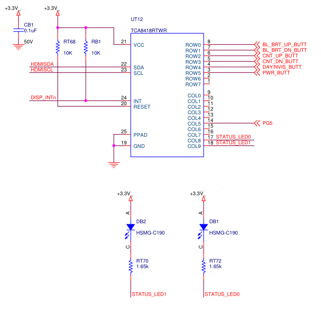
    I have attached a portion of the schematic of our setup below.  Note that while not shown below, all the buttons are pulled high via external 10k resistors.  The connections labeled STATUS_LED are outputs.  PG is simply an input that does not need to be tied to the GPI_INT.

  • Hello,

    Your parenthesis do correctly mask and shift the bit, all is good there.

    There are a few things that you mention that make me think there is a configuration issue.

    I am now seeing each read  of the INT_STAT register returns 0x03 (GPI_INT and KE_INT high) regardless of if I attempt to clear the FIFO and Interrupts afterward.  Should I be attempting to clear interrupts before or after I perform the read of the GPI?

    - The procedure to clear these interrupts is to read the GPIO_INT_STAT registers (0x11-0x13), read the FIFO until 0x00, then writing a 0xFF or 0x03 (shouldn't matter) to 0x02.

    If these bits are getting set constantly, and reads to the FIFO result in non 0x00 values, it means that it is interpreting something as a falling edge.

    I made the change you suggested in ensuring the FIFO is clear before clearing out interrupts.  Each time I read the FIFO I get 0x15, then the next read comes back with 0x00.  My ensuing read of the GPI_DAT_STAT (0x14) results in 0x03, which is incorrect, I have confirmed all the GPI signals are being held high.  Again, if I remove any interrupt polling, and simply poll the GPI_DAT_STAT register, the values are correct.

    - I find this one interesting. 0x15 is a keyscan mode value, not a GPI. This value should not ever pop up if your registers are configured to have everything in GPIO mode. Is there a way for you to confirm the values in the TCA8418 registers? Perhaps by reading the registers back to you via console/UART or something?

    I have attached a portion of the schematic of our setup below.  Note that while not shown below, all the buttons are pulled high via external 10k resistors.  The connections labeled STATUS_LED are outputs.  PG is simply an input that does not need to be tied to the GPI_INT.

    - Thanks for the schematic, I do not see anything incorrect here. You mention each button has an external 10k pull up. Is it pulled up to the same 3.3V rail? Also, since you have external pull ups, you can disable the internal pull ups to save some power by writing 0x3F to register 0x2C.

    Additional Question: I notice you use the INT pin out of the 8418? Is there a reason you prefer to poll instead of using the interrupt pin to trigger appropriate reads of the device?

  • Apologies for not getting back to you sooner.  I've had other projects come up and take priority over this one involving the TCA8418
    I'll be able to give these most recent suggestions a try late this week/early next week.

    To answer your question about the INT pin, the original intention WAS to use the INT pin, however the part that was chosen to read the TCA8418 via i2c is the same device we wanted to use to monitor the INT pin.  This part was discovered to not be able to function as a serial device while at the same time reading the INT pin.  This leaves us forced to use a software solution of polling the interrupt, at least until the hardware I have is changed, which may or may not occur.