This thread has been locked.

If you have a related question, please click the "Ask a related question" button in the top right corner. The newly created question will be automatically linked to this question.

PCA9555 Output/Input registers disagree.

Other Parts Discussed in Thread: PCA9555, TCA9555

I have a PCA9555 in my system to expand some GPIO for LEDs and to switch some transistors, etc.

The problem I am seeing is that some of the OUTPUT pins are not read correctly by the INPUT register..

In my code I test the outputs for a stuck condition by setting the output, and comparing the output register value for that bit, to the input register. They should never disagree unless there is some external condition holding the pin. However, on this particular output, once I set it HIGH the input register ALWAYS reads "1" for the bit, even if set to "0".

I watch the output on the scope, and it always swicthes. The input register for the bit does not follow the state of the output for the pin.

What up TI?

  • Eldon,

    Do you have the register map of the settings you are using? Can you provide the scope shot that you are seeing switch and the corresponding register reads that is reporting incorrectly?

    Thank you,
    Adam
  • Well... things are clear now what is going. The scope trace kinda tells the story... The following printf section shows the register dump of the device when the error state is noted. This check is done in my driver each time a PCA9555 reg is read.

    **************************************
    Expander pin 0x0040 is in ERROR STATE!
    **************************************
    Output reg : 0x3808
    Input reg : 0x3a78
    Invert reg : 0x0000
    Config reg : 0x0230

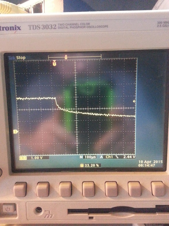
    I am guessing that the PCA9555 needs a minimum load connected output to drain charge away on a switch from high to low state. This is the scope trace...

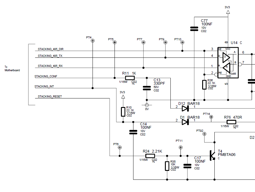
    The connected line schematic is show below as STACKING_CONF line. And there is nothing else connected to the line at the other end. So R11 and C13 are the load at this point. ....

  • Hello,

    I find this interesting. The PCA9555 has internal MOSFETs to pull up or pull down the line as needed. No external load should be necessary. It also has an internal pull up to prevent floating input issues.

    Are you having this issue on multiple boards? Is it possible to replace the device and see if this port is damaged?

    Also, in your schematic, does that line get pulled up somehow? Perhaps there is some discharge RC constant in place with your series R and the capacitor. It's difficult to guess with this snippet of the circuit.

  • Hi Jonathan,

    We are having this problem on multiple boards. The scope output looks exactly the same on both boards I have.

    There is nothing more to right of that line in the schematic. It just goes to a connector.

    Thanks for your interest,

    Eldon.

  • Eldon,

    Could you test for me and see if this behavior goes away if you put a load on the port?
  • Jonathan,

    I have a question about this issue... seeing as I have that scope trace showing the line decay time being excessively long.

    If I do another read on this port, many seconds later, the INPUT register still reads HIGH for that line. That doesn't make sense as the decay time is about 8 mS. Successive reads should show the line being low. But it always comes back high.

    The scope trace shows the line maintaining LOW state. Shouldn't another read show the correct state?

    I'll get a load on that line today, and post the results.
  • When your scope shows a low but your input register shows a high, can you tell me what the scope is showing the voltage at on the pin? Is it within the valid VIL spec (0.3 * VCC)? Do you have the ability to check the voltage/waveform at the pin of the device? Or are your test points on the same node? I'm interested in seeing the voltage that doesn't go through the diode or pull up.

    You are correct that a read triggers the read sampling, so a successive read should show the line low if the voltage applied to it is within VIL spec.
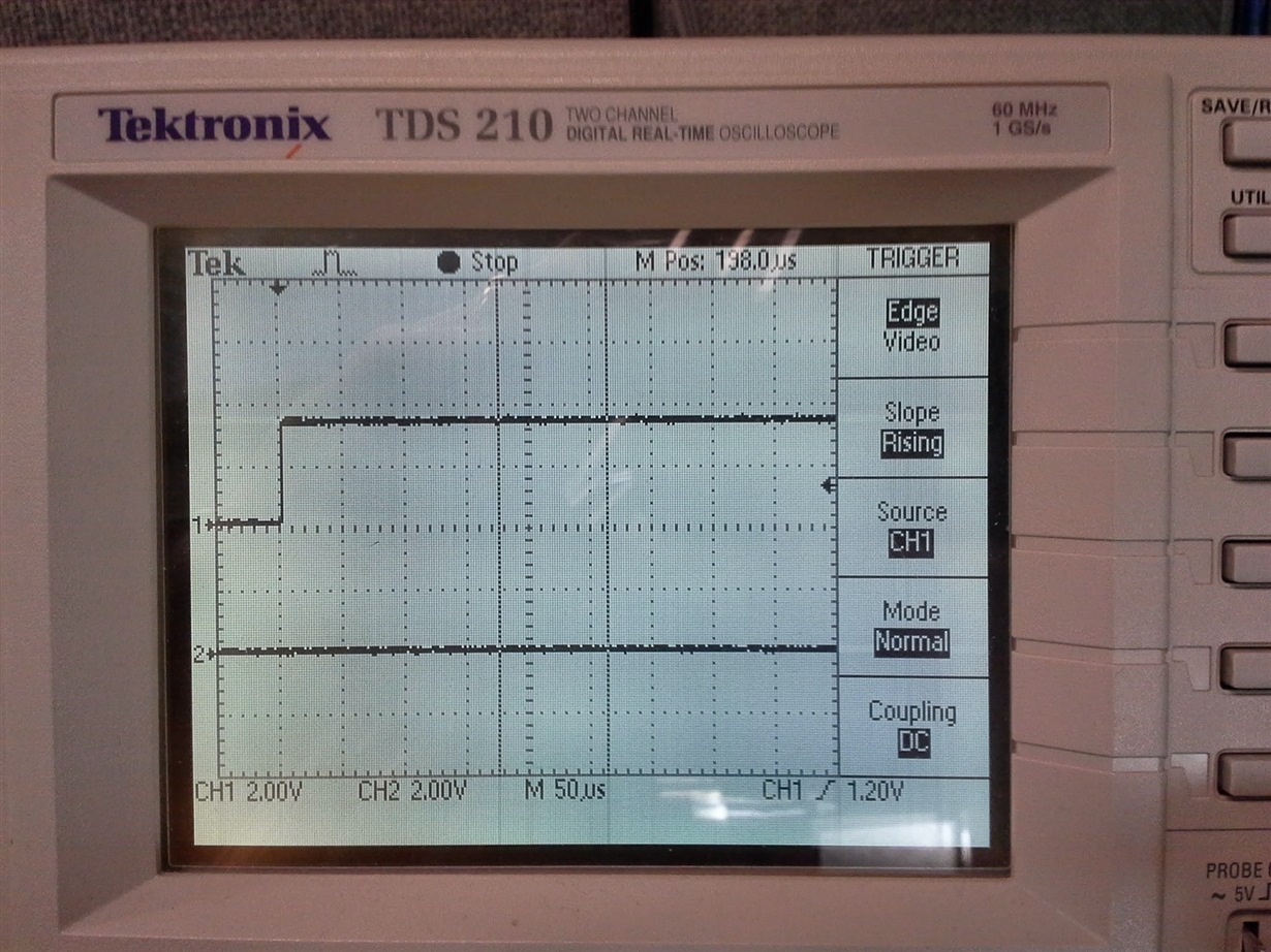
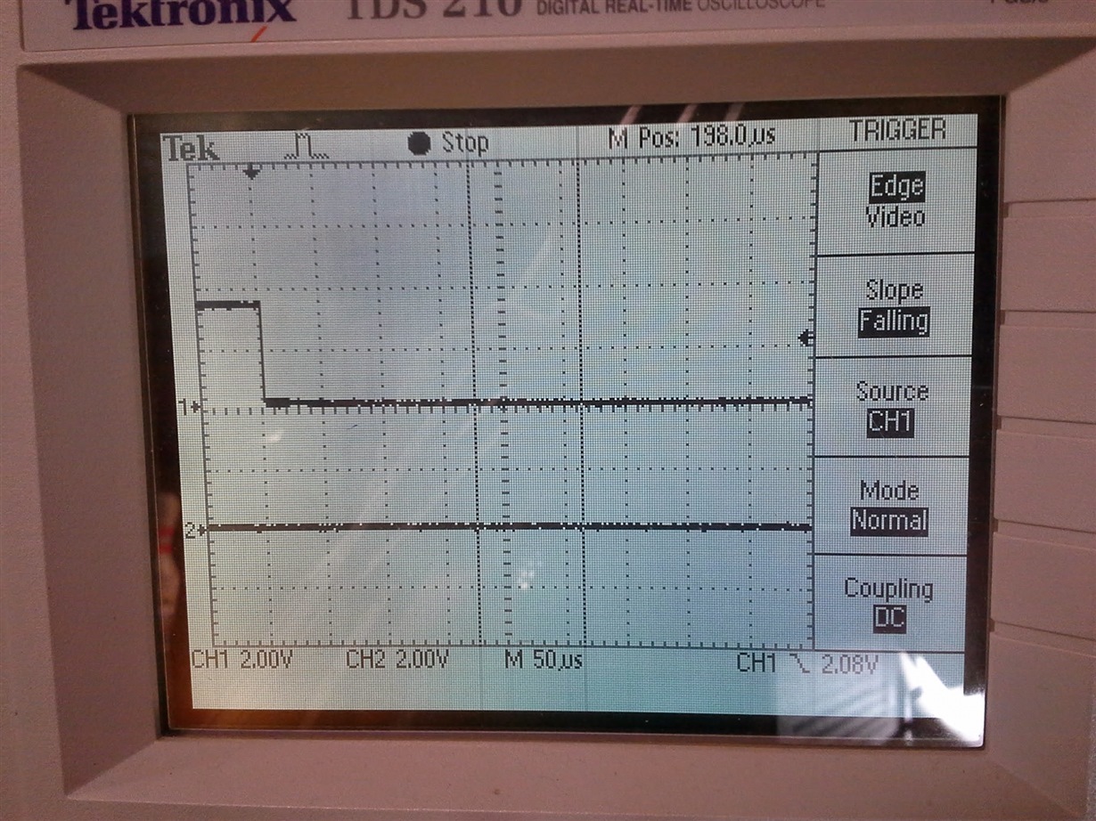
  • Here is the result of setting both HIGH and LOW states on the output, read directly at the port pin.

    Regardless of pin actual state, the INPUT register reads this pin as HIGH once it has been set HIGH. Basically, once the pin has been set HIGH, it always reads back HIGH regardless of pin state. Seeing as the bit I am reading is in the middle of a bytes, I don't think there is anything wrong with the I2C communication that would give this error condition.

  • The waveform looks ok.

    Could you post your register settings/what commands you are sending during initialization?
    I'd like to take a look at the software side of things to see if it gives a hint at what's going on.
  • When I init the device I send the following sequence...

    void ExpanderConfig(void)
    {
    ExpanderWrite(EXPANDER_CONFIG_PORT_0, config);
    ExpanderWrite(EXPANDER_OUTPUT_PORT_0, outputs);
    ExpanderWrite(EXPANDER_INVERT_PORT_0, (unsigned short)0);

    ExpanderRead(EXPANDER_INPUT_PORT_0, &inputs);
    ExpanderRead(EXPANDER_OUTPUT_PORT_0, &outputs);
    }

    The config word is initialized to 0x0230
    The outputs word is initialized to 0x3808
    And Invert is 0x0000

    Then I do a read of the input and output register pair to ensure my input word is a reflection of external inputs.

    Output reg : 0x3808
    Input reg : 0x3a38
    Invert reg : 0x0000
    Config reg : 0x0230

    Then I set bit 0x0040 HIGH. and it reads back 0x3a78 which is correct.
    Then I set bit 0x0040 LOW and it still reads back 0x3a78... which is INCORRECT. However, on the scope the line state is LOW. And from the last scope trace at the pin, it takes but a uSec to decay from 3V3 to 0V.
  • My project lead had a question as to whether I was setting and then reading back the device too quickly, but we run the I2C bus here at 100KHz. And at least 2 bytes must be transmitted before the read (device address and register address) and that give a minimum of bound of 220 uS between write and read.

    The datasheet doesn't say anything about output to readback timing, but fairly certain 250 uS is plenty of time for the output to settle before a read clock comes by.

    Plus the fact that, if that were the case, successive reads would solve that issue. But onvce this bit is set HIGH it always reads back as HIGH, regardless of pin output state.
  • I don't see anything of concern with how you're doing this.

    Is it possible a register value is getting changed in a driver? Putting a resistive load on the pin to pull it down, does it not pull the input register low? Can you try rewriting the configuration word and then rewriting the output register to see if this changes anything?

    I do not have any PCA9555s laying around to test this myself, I have TCA9555, which is an equivalent with performance enhancements. Currently waiting for some PCA9555s to get sent to me so that I may test this issue myself.

    I would see if you can verify with a scope that the data going between the two devices is indeed what we'd expect. Several scopes have the ability to decode an I2C transaction and read the data right to you.
  • I have verified the read value directly from the I2C read function... the value read back is correct.

    I tried a write of the config register before writing the output reg value. That changed nothing.

    We have decoded the I2C stream previously, and all is correct. We use this I2C channel to read/write to several devices on the bus. All behave as expected with respect to I2C data streams.
  • Thank you Eldon.

    I am awaiting my samples to try myself. This being an issue I've not encountered, I am not sure what other suggestions I can offer until I can try to duplicate the issue in my lab.

    Is this a new design, by any chance? Typically, we recommend that the latest version of a device be used, in this case, the latest version would be the TCA9555. There are some general performance improvements over the PCA9555.