This thread has been locked.

If you have a related question, please click the "Ask a related question" button in the top right corner. The newly created question will be automatically linked to this question.

PCA9548 primary pull up resistor value?

Other Parts Discussed in Thread: TCA9548A

Hi,


We have a PCA9548 connected to an FPGA with 10K pull ups to 3V3. On the other side the I2C channels are connected to other boards with 3K3 pull up to 3V3.


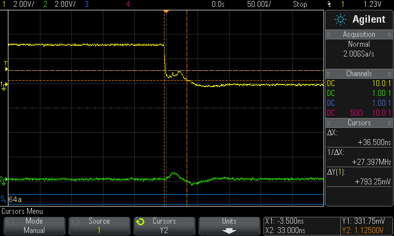
We are having a problem with what appears to be a reflection that causes the bus to reset. On the output it appears are ringing and on the input to the switch from the FPGA the "ring" is inverted and at 1.5 v probably close to a threshold. See picture below


Is 10K a good pull up value for the locally connected switch?

Should the other side be matched or stronger pull up?

The signal is marginally improved by separating the I2C ribbon cable so SDA and CLK do not couple as closely. Ribbon has SDA,3V3,SCL,0V in that order.

Thanks

  • Hello Andrew,

    Thank you for your question. First, I'd like to point out that we recommend the use of the updated part, the TCA9548A is an update to the PCA part, where a POR errata has been fixed, as well as lower voltages are supported, as well as general performance improvements. If you see a PCA and a TCA version of the same part, the TCA part is the newer/updated one.

    Next, there is no picture attached. To attach a picture, you can press the "use rich formatting" button to the bottom right of the reply box at the bottom to open up the fully featured reply box. There is then an icon of an image next to the paperclip that you may upload an image with. You must upload, and wait for the image to appear in the pop-up before pressing OK.

    Next, your ringing is likely a result of the mismatched pull-up resistor values. Since the PCA9548 is NOT a buffered device, this means that your total current a device must sink on the bus is the sum of the number of channels connected and their resistance of pull-ups.

    For example, if you have SD0, SD1, and SD2 channels connected, each with a 5k pull-up resistor to a 3.3V rail, and you also have a 5k pull-up resistor on the SDA line, then any device wishing to transmit a 0 will have to sink:
    3.3V / 5k = 660 uA (Same for all lines since they're all the same pull-up value)
    Take this value and multiply it by the lines, 4 lines (include SDA line as well) and we have a total of 2.64 mA that a device will have to sink.

    So you will need to keep this in mind if you plant o have multiple devices connected at once.
  • Hi,

    We are only talking to one bus at a time. Do you still need to take into account the parallel resistance of all the buses?

    Here is the picture again. Ch1 is SDA and Ch2 is CLK

    Thanks

  • Hello,

    If you only connect 1 bus at a time, then you do NOT need to take into account the parallel resistance of all the buses, only of the buses that are connected at a time.

    Thanks for uploading the photo.

    You indeed appear to have some crosstalk.

    Since the PCA9548 is unbuffered, this is likely a result of the mis-matched pull-up resistor values. Also, I believe you are seeing an inductive effect as well from long wires/traces since you are getting some undershoot as well.