This thread has been locked.

If you have a related question, please click the "Ask a related question" button in the top right corner. The newly created question will be automatically linked to this question.

LSF0101 Question

Other Parts Discussed in Thread: LSF0101, LSF0108, SN74LV4T125

Hi Team,

My customer has the question below.

According to below document, it mentions that Vref_B should be 0.8V higher than Vref_A on LSF0101.

http://www.ti.com/lit/an/slva675a/slva675a.pdf

Since most of the level translator only require Vref_B>= Vref_A, can you help me know why LSF0101 has such special requirement?


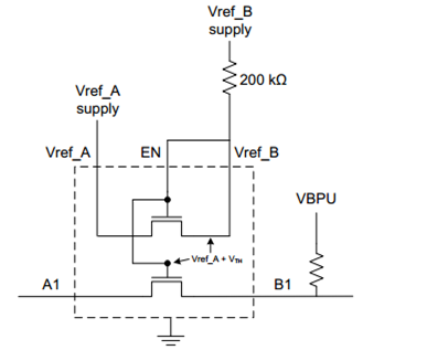
Moreover, it shows there’s a pulled up resistor for both EN and Vref_B pin, can you help confirm why the pulled up resistor is not put only for EN pin?

Besides, as we see some voltage leakage from Vref_B to Vref_A through this level translator, will there be any issue if we connect EN pin to Vref_A?

Please help on this.

Thanks.

  • Hi Prescott,

    LSF0101 is different from other level translators because the LSF0101 is a FET switch that turns off when the input signal approaches Vref_A, then allows pullups to translate the logic level.

    Other dual-supply translators are designed as logic gate transceivers/buffers that use the supply voltages to output the appropriate voltages. Those types of translators have a small amount of inherent current drive, while the LSF0101 does not.

    Customers must tie EN and Vref_B together and pullup using 200k for two reasons:
    1. The large resistor allows a VGS voltage drop across the reference FET without excessive current leakage. The FET will have a voltage drop of ~0.8 V across itself (like a diode). Therefore, the "B side" of the reference FET will be pulled up to Vref_A + 0.8 V.
    2. Connecting EN to the "B side" of the reference FET will bias the gate to Vref_A + 0.8. The gate of the reference FET is connected to the gates of all the channel FETs. This will allow the channel FETs to start going high-impedance once the input approaches Vref_A. In addition, the VGS of Vref_A + 0.8 V will cause the output of the channel FETs to equal Vref_A - even without any pullups. However, due to the high impedance of the FET, translating down without a pullup is only recommended at very light loads (at least hundreds of kOHM).

    -Ryan
  • Level Translation is new for me. I want to connect a CMOS camera sensor that runs on 1.8V to my MCU that runs on 3.3V. 8-bit pixel data, the vsync and hsync signals are one direction, but there are other signals like I2C for camera management, power down and reset signals that are in both directions. Searching the web I found the LSF0108 which delivers 8 bits (I need two of them and I have enough bits to run my application) and seems to be very fast. 

    I had a bit of trouble to get this device up and running:

    LSF0108PWR translates 3.3V not to 1.8V as expected but to 2.5V

    But it's working fine now. In this post you say: "Those types of translators have a small amount of inherent current drive, while the LSF0101 does not.". What does that mean? Is inherent current drive a problem? In what applications?

    I am not sure if I really selected to correct device for my application. Any TI-Level-Translators that better fit my needs? Thanks for your help.

    Phillip

  • Hi Phillip, "Inherent current drive" means that the device itself can provide current out of its output port to drive a load. It also means that a device can "sink" current into its input port. The more current drive a device has, the better performance it has at higher loads/capacitances. Current drive is generally a good thing. Logic gates are examples of devices that have current drive at their outputs. Signal switches (FET switches) are examples of devices that do not have current drive at their I/Os. They act like resistors when they are on.

    In translating a signal to go into a logic input of another device, like another gate, high current drive is not really necessary because most logic inputs are high-impedance (very very light loads).

    The LSF family of devices cannot source or sink current at all; they are just FET switches. They turn off when the input on one side is high (allowing the other side to pull up through the Resistor), and they turn on when the input is low (allowing current to flow through the LSF FET to the current-sinking device, pulling down the voltage on both sides of the device).

    The LSF is an excellent choice for bi-directional translation. For single-direction, you can use a device like the SN74LV4T125 to translate up from 1.8 to 3.3 V, or translate down to any valid VCC level. The LV4T has a current drive of 8-mA, so it can handle a bit of a load on its output.

    -Ryan