This thread has been locked.

If you have a related question, please click the "Ask a related question" button in the top right corner. The newly created question will be automatically linked to this question.

The LSF0108 cannot reach 3.3V for 50MCLk when using under 1.8V to 3.3V

Other Parts Discussed in Thread: LSF0108, TXB0106, TXS0206

I’m now verifying the LSF0108 on my board to check if it can support 50MHz. Now it can work. But the waveform is a little strange.

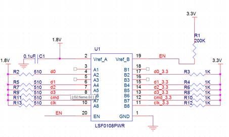
Here is the schematic.


I used the pull up resistor based on the table in datasheet. The behavior is different for different signal.

  • 3.3V Pullup 1K, 1.8V Pull up 510ohm

  • Data is OK

  • 50M CLK cannot pass from 1.8V to 3.3V

  • CMD is only 2.0V when the CMD pass from 1.8V to 3.3V.

  • 3.3V Pullup 1K, 1.8V pull up 180ohm for CMD. It is OK

  • No 3.3V Pullup, 1.8V pull up 680ohm for CLK. Clk is single direction signal and only pass from 1.8V to 3.3V side. The CLK is only 2.0V on 3.3V side. But the card can work.  When I reduce the 1.8V pull up to 180ohm, the low level of the CLK on both side increase to 1V. I cannot get a suitable configuration for the clock. Do you know why?


  • Reuben,

    Are your inputs on the 1.8 V side being driven high by another part or are the pull-up resistors doing the work?  I'm wondering because you shouldn't need those pull-ups to make this circuit function (try removing them and see if it affects functionality).

    The LSF0108 uses a simple FET switch for translation.  When the input voltage approaches Vcca, the FET switch turns off and the output goes high impedance, allowing the line to be pulled high by the pull-up resistor.  So, in the case you describe with no pull-up on the 3.3V CLK line, it would be impossible for the translation to work.  The output would just be clamped to the highest voltage that will pass through the FET (Vcca - Vgs).

  • Hi Emrys,

    You are right. I'm sorry that I give the wrong resistor position. It should be

    No 1.8V pull resistor, 3.3V pull up 680ohm for CLK.  One FPGA connect to the MicroSD card on my board. There is no other parts.

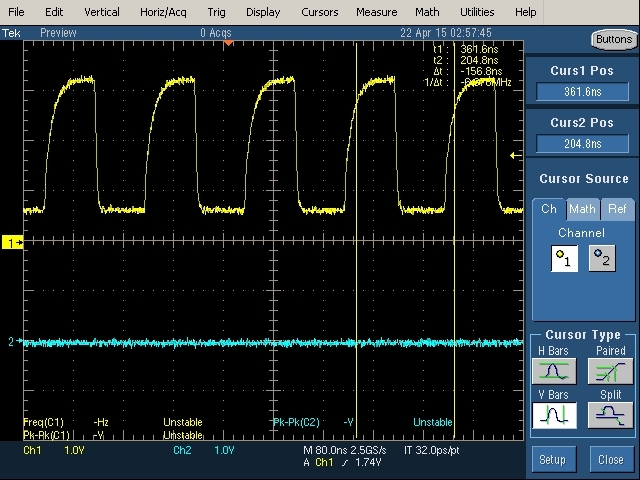
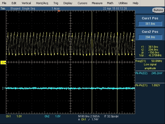
    I add the waveform for different frequency on 3.3V side. For low frequency, here is 6MHz, the voltage is correct. But for 50MHz, the max voltage is only 2.2V.  It is OK for 3.3V signal but no more margin.


    Best Regards

    Reuben

  • The output high level will be dependent on the RC characteristics of the output. Lowering the line capacitance or the pullup resistance will reduce the rise time on the output. If this is not possible, you might want consider going with a different type of translation part -- perhaps one with an internal drive structure. Please let me know if you need additonal assistance!
  • Hi Reuben

    If you are still running into issues, you could take a look at TXS0206?

    Thanks

  • Hi Jennifer,
    The package of TXS0206 is not suitable for me. I used the TXB0106 in the first revision. It can not reach 50MHz.
  • Hi Emrys,
    How to reduce the RC characteristics of the line. Now the LSF0108 connect to SD card directly? There is only a ESD device(ESD5V3U2U) parallel connect to the line.

    Best Regards
    Reuben
  • The only ways are to make the line physically smaller (narrower, shorter) and to reduce the pull-up resistor value. The amount of reduction will depend on how much current the output device can sink during operation.
  • Hi Emrys,

    I reduce the pullup resistor. Now the waveform is better.

    Thanks.