This thread has been locked.

If you have a related question, please click the "Ask a related question" button in the top right corner. The newly created question will be automatically linked to this question.

TXB0106 A5 pin floating issue

Other Parts Discussed in Thread: TXB0106

Hi,


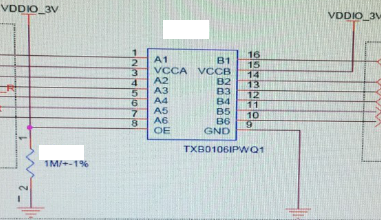
My customer used TXB0106 in their circut. They forgot to remove B5 pin for a MCU's reset signal and the A5 pin is be floating.

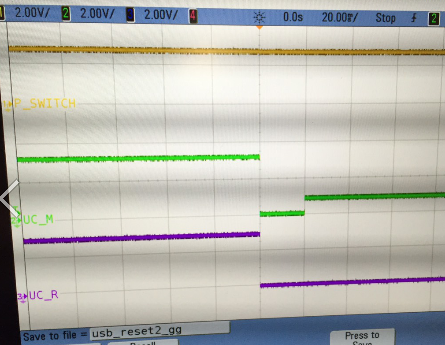
They found when they press the #reset button to GND the voltage will be GND, when they release the button, the signal won't become 3.3V, it's only 1V.

It is A5 pin be floating issue? Thanks!

  • Hello Jerry,
    When you say the "signal won't become 3.3V, its only 1V", are you saying A5 or B5 pins stays at 1V? Do you have a schematic? or waveforms of the signals when this happens?
    -Francis Houde
  • Hi Francis,

    You can see the below information. Thanks!

    Green for B5

    Blue for A5

  • Hi Francis,
    How about it? Thanks!
  • Hello Jerry,
    Sorry for the delay. I want to make sure I understand the conditions and the sequence of what is happening.
    1. B5 is connected to the Reset pin of MCU, correct?
    2. A5 is floating
    3. VCCB = VDDIO_3V=3.3V? Is VDDIO_3V a 3.3V bus???
    4. VCCA =???
    5. Where are the decoupling caps on VCCA and VCCB? I can't see it on the schematic. Do you have a better schematic?
    6. It looks like OE is connected to VCCB? Is that correct? Why is it not connected to VCCA? It is referenced to VCCA.
    7. Do the supply rails go away during reset?
    8. I am assuming that whe you say "Blue for A5", do you mean purple, it looks like purple to me.
    9. You need to find out what happens to the reset port of the MCU during and after reset? Does it have an internal pull down? Is the voltage on B5 below the VOH level?

    those are some of the questions I have to try and understand what is going on in your circuit.
    -Francis Houde

  • Hi Francis,

    Thanks for your help. FYI

    1. B5 is connected to the Reset pin of MCU, correct? --- Yes!
    2. A5 is floating --- Yes!
    3. VCCB = VDDIO_3V=3.3V? Is VDDIO_3V a 3.3V bus???
    4. VCCA =???

    Jerry: I have asked them to change the voltage for VCCA(2.8V)<=VCCB(3.0V)


    5. Where are the decoupling caps on VCCA and VCCB? I can't see it on the schematic. Do you have a better schematic?

    Jerry: There have 0.1uF.


    6. It looks like OE is connected to VCCB? Is that correct? Why is it not connected to VCCA? It is referenced to VCCA.

    Jerry: I have ased them to change it. But it's the same result.


    7. Do the supply rails go away during reset?

    Jerry: During power-up sequencing, VCCA ≥ VCCB.


    8. I am assuming that whe you say "Blue for A5", do you mean purple, it looks like purple to me.

    Jerry: You are right. It's purple.


    9. You need to find out what happens to the reset port of the MCU during and after reset? Does it have an internal pull down? Is the voltage on B5 below the VOH level?

    Jerry: If they try to be floating B5, the reset is normal.

  • 9. Do you know if the signal on B5 is below VOL? What kind of pin is the Reset pin of the micro? Output? What kind? Open Drain or Push Pull?