This thread has been locked.

If you have a related question, please click the "Ask a related question" button in the top right corner. The newly created question will be automatically linked to this question.

TXB0104 Oscillation Problem

Other Parts Discussed in Thread: TXB0104, SN74LVC2G17

I have a board with a processor on it that has 4 GPIO pins connected to port A of a TXB0104.  Port B of the TXB0104 is connected to a connector that connects to a cable that goes off board.  The cable is about 3 inches long.

The processor and port A of the TXB0104 can be powered at either 1.8V or 3.3V.  Port B is powered at 3.3V.  When the processor and port A are at 1.8V, everything works fine.  However, when the processor and port A are at 3.3V, I get oscillations during certain transitions.  For example, when the external cable has a signal transition from high to low (i.e. a port B signal is driven low which should translate to port A), that signal starts to oscillate at around a 27ns period.  I am driving that port B signal with a TI SN74LVC2G17 chip.  I inserted a 100 Ohm resistor between the output of the SN74LVC2G17 and the TXB0104 as a test and saw the oscillation still occuring, but only on the TXB0104 side.  In other words, the output of the SN74LVC2G17 was stable but the other side of the resistor (connected to the TXB0104) still oscillates on the hight to low transitions.

Another example of the oscillation issue is when I drove a signal on the processor side (TXB0104 port A) from a low to a high.  In that case I had the signal on the port B side oscillate just as the previous example.  I haven't probed the port A side of the TXB0104 yet because it is not easy to get to but I could if necessary.

So my question is, how can I avoid this oscillation problem? I am stuck with the board that has the TXB0104 but I can put whatever I want on the other end of the cable.  I can add a choke or something if that would help (haven't tried yet).  Based on the datasheet, it sounds like my problem is due to the fact that I have too much capacitance on the port B side of the TXB0104 because that can cause "O.S. retriggering, bus contention, output signal oscillations". I can't remove capacitance caused by cables, connectors, long traces but I can add anything to the cable side.  Any suggestions or help is greatly appreciated.

I saw some posts with similar issues to mine but none seemed to have an answer I could use.

Thanks,

Nick

  • Nick,

    One of the layout notes is to keep the length between the TXB0104 and the target device to within 10 ns. This prevents any signal reflections from accidentially triggering the one-shots, which can then lead to output oscillations. One approach would be to reduce any signal reflections in the channel, as that may be causing the oscillation.

    If you are able to share your schematic and oscilloscope waveform captures, I can review them and provide you with more feedback. Thanks.

    Best Regards,
    Nirav
  • Understood about the max trace length.  That was an oversight on my part. Unfortunately I am stuck with this board as it is so I have to find a way to fix it with a second board.  Any advice on how to reduce reflections would be greatly appreciated.  

    Below is the schematic of the board that has the TXB0104 on it.  Note that Vmain is either 1.8V or 3.3V.  J1 is used to connect via a cable to the second board.

    Below is the schematic for the second board.  The User_GPIO_* signals on the first board connect to the GPIO*_Device signals on the second board below.  Note that on this board Voutbuff is 3.3V.

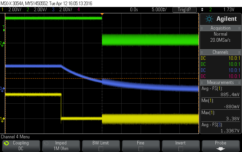
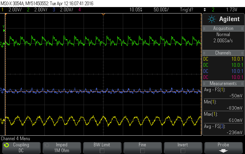
    I test the first 2 signals by using the microcontroller to drive User_GPIO_[1,2]_MCU high or low.  I test the last 2 signsl by using a bench power supply to drive GPIO[1,2]_Ext high or low.  Below are 2 screenshots from an oscilloscope for the GPIO3 signals.  The yellow trace is GPIO3_Ext, the blue trace is GPIO3_Filtered, and the green trace is GPIO3_Device.  The first capture is on a larger timescale to see the entire transition of signals.  The second capture is a closeup of the oscillation.  I do not have captures of the signals on the first board (User_GPIO3 or User_GPIO3_MCU).  User_GPIO_3 should be very similar to GPIO3_Device since they are connected via cable.  I expect that User_GPIO_3_MCU is oscillating too but at higher voltage swings.  I know this because I am getting interrupts on the microcontroller faster than I can handle them.  That is the real problem here.

    I hope this is enough to help.  If there is anything else you could use to help figure this out, I'd greatly appreciate it.

    Thanks,
    Nick