This thread has been locked.

If you have a related question, please click the "Ask a related question" button in the top right corner. The newly created question will be automatically linked to this question.

MAX3221 receiver problem

Other Parts Discussed in Thread: MAX3221, MAX3221E

I am using the MAX3221 to interface between a computer and a microcontroller.

I have the:

FORCEON pin low

/FORCEOFF pin high 

/EN pin low

I have a valid level on the receiver input and verified that the /VALID pin is high, indicating a valid level. Also, the transmitter from the microcontroller is working properly, data sent from the microcontroller is making it into my hyperterminal window. The problem is that data coming from the computer isn't making it through the receiver of the MAX3221. The receiver input signal looks fine, going between -6.5V and +6.5V, but the receiver output is not doing anything, it seems to be in the high-impedance state or, maybe, shutdown state.I wouldn't think it is in shutdown because the transmitter is still functioning.

Any ideas why the receiver isn't working?


  • Richard,

    If VCC is on and ~EN is low then the ROUT should be active. Measure the voltage on pin 1 and pin 9 at the device pins.

    Regards,
    Ron Michallick


  • Hi Ron,


    Pin 1 is at 0V.

    Pin 9 is also at 0V, even though pin 8 is at -6.5V when connected to the PC. I would think pin 9 should be at 5V at that point.

    Pin 10 is at 5V, so the chip thinks the input is valid.

    When I send data from my PC into pin 8, pin 9 stays at 0V. Pin 9 appears to be floating because if I put a 10k pullup to 5V, it will go to 5V.

    Is there anything other than enable that can turn the receiver off?

  • Richard,

    If there was a disconnect inside the MAX3221, that would be the result.
    Can you try a second unit?

    Ron


  • Hi All,

    I have a similar problem so I am hoping Ron Michallick is watching as he answered the previous MAX3221E question. Sorry for hijacking a previous question, but the problem is similar so I think it is appropriate.

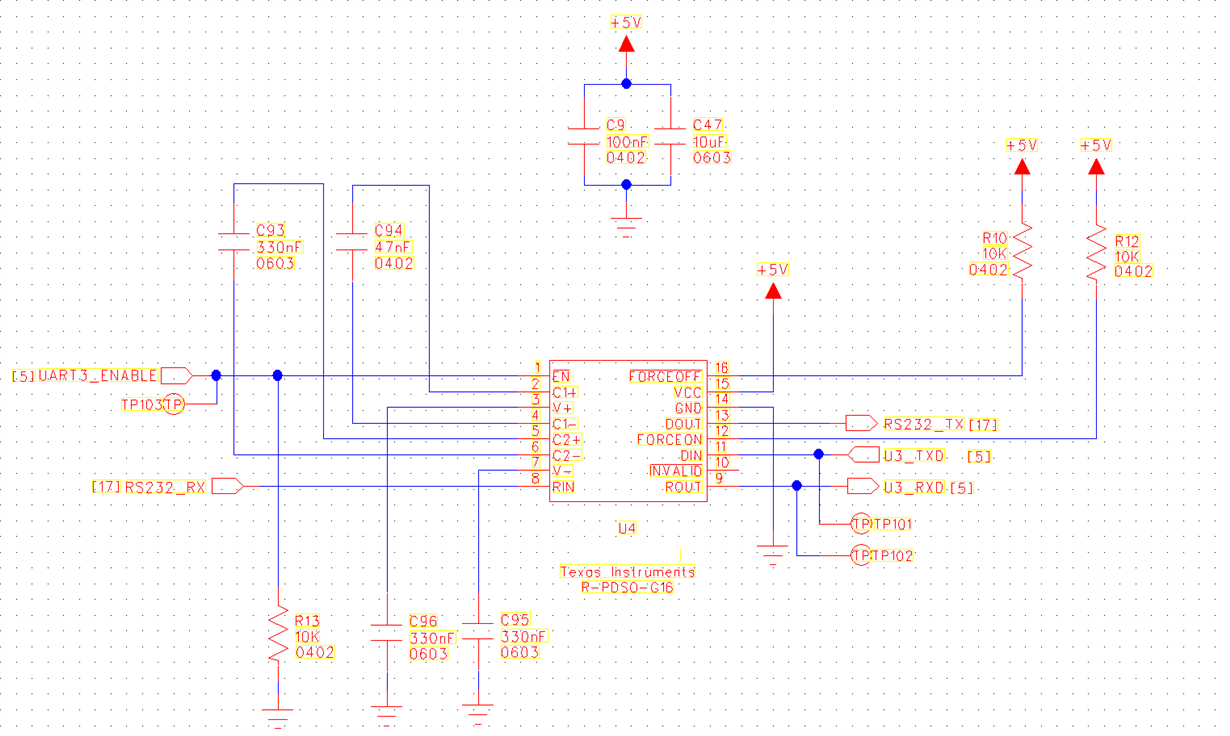
    I have an RS232 circuit that is not working properly:

    This circuit is not transmitting from the microprocessor's signal from the U3_TxD pin to the RS232_Tx pin. The RS232_Tx output voltage is 0V, not +/-Volts.

    My configuration is to inhibit the auto-powerdown function by pulling the FORCE pins high.

    The microprocessor signals are 3V3 but the datasheet says these logic levels should work okay. It is powered from 5V so I have used the cap values recommended for 5V in the datasheet.

    The transceiver transmit function refuses to start when powered on. We have noticed that when pin2 and pin3 are shorted briefly, then the chip starts to transmit correctly and the RS232_Tx signal goes negative.

    Has anyone got any ideas why the chip isn't starting to transmit.

  • Picture of schematic:

  • Murdo,

    Can you try to attach schematic again?

    The data sheet says 5V logic input is OK with VCC at 3.3V.
    Nevertheless VIH higher than 2.4V and VIL less than 0.8V will work with VCC at 5V.

    With VCC at 5V and both force pins logic high then the DOUT pin will be powered.

    Can you report the voltage on pins 3, 7, 12, 14, 15, and 16?
  • Thank you for responding so quickly Ron,

    I also assumed from the Vih and Vil that we would be okay.

    I will try to get measurements and post them later - the board is being used by one of the firmware guys and I don't want to delay him. I'll make the measurements when he leaves for the evening.

    The board is the second version of our new product: the first version worked okay, but as far as I can see there were no changes except adding the three test points.

    Thanks again,

    Murdo.

  • Hi Ron,

    I have taken some screenshots from the 'scope and measured all the pins on the board which is not working properly.

    I also took 'scope shots from a prototype board we made which appeared to be working okay.

    See attached.

    Many thanks,

    Murdo.

    RS232 Problems.docx

  • I am hoping to not have to remove components as we only have three boards for three firmware engineers. IS there anything you can suggest to test if the caps, etc are good?
  • Murdo,

    The data was very helpful.

    Operation is like this; basically VCC charges C1; C1 + VCC charges V+; V+ charges C2; C2 charges V-.

    V+ is 4V so the positive boost (C1) is not correct.
    V- is same as inverted V+ so negative 'boost' (C2) is good.
    Pin C1- should be GND and VCC and it is, so that's good.
    Pin C1+ should be VCC and V+ and it is, so that's good.

    However, V+ is less than VCC despite all signals looking functional.
    Therefore I believe that the 33nF capacitor does not make good connection to MAX3221 pins 2 and 4.
    Check solder connections and continuity.
  • SOLUTION!

    Hello Ron,

    Many thanks for your help. That was indeed the problem. I and two colleagues had both checked the PCB visually and we couldn't see any problems - the solder fillets were not neat but they were there. As soon as I de-soldered it, cleaned the pads and soldered the cap back in place it started working the same as the previous good board (and all without interrupting the firmware guys).

    Many thanks Ron,

    Murdo.

    For future people - Lessons on RS232 Transceiver Problems:

    They usually just work out of the box.

    Check soldering, then check it sideways with a microscope, or beep it out between component end caps.

    Check the states of ForceOn and ForceOff, and the enable pin.

    Check each stage as Ron suggests:

    • Is V+ as expected (ie higher than Vcc)?, if so the positive boost cap is good.
    • Is V- the same as inverted V+? If so the negative 'boost' cap is good.
    • Is Pin C1- oscillating between GND and VCC, if so that's good.
    • Is Pin C1+ oscillating between VCC and V+ and it is, so that's good.