This thread has been locked.

If you have a related question, please click the "Ask a related question" button in the top right corner. The newly created question will be automatically linked to this question.

SN65HVD3082E IC is failing

Other Parts Discussed in Thread: SN65HVD3082E

Dear All,

One of my customer is using SN65HVD3082EDR in AC-DC Power supply unit for telecom applications ,

Certain units are failing for communication, in which

  1. 30% is the failure of the RS485 IC along with the 4ohm resistors and the 15.8V ESD diode are damaged
  2. 100% of the failures the 4ohm resistors are damaged ,i.e, its showing in the range of Mega ohms or in other words are opening.


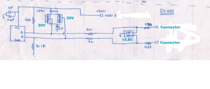
Please help us review this circuit attached and suggest changes if any in the protection side of things.

They have two diodes of 5.6V one each connected to the ground and +5V respectively. Along with the 5.6V diodes we have a 30V diode included for protection towards the IC end. The ESD diode used at the connector end is of 15.8V.


Aravind.

  • A couple of things
    (a) RS485 needs a ground, so your "connector" should have A , B , GND
    (b) Most designers use 7.5v (bidirectional) TVS protectors where you have 15.8v, also the SOT23 size TVS are quite fragile, if you want to run the RS485 cable in an industrial plant, you will need SMB sized TVS ( SMBJ7v5CA) These have a lot of capacitance , so don't expect more than 19200baud. Note the absolute maximum ratings for the SN65HVD3082E is -9 to 14v on A and B. Have a close look at your TVS data sheet, the clamping voltage can be double the nominal operating voltage.
    (c) The 30v diodes don't make sense unless they are schottky diodes.
    (d) You can use bigger resistors instead of 4ohm, like 22ohm or even 47 ohm, you will get a better match to the line impedance too.
    (e) Telecoms use an odd earthing arrangement for the 48v supply , the positive line is normally connected to an earthing rod, while the negative line is then 48v below "earth" , so you could get 48VDC on your "connectors" by connecting to a grounded computer.
    (f) If you are attempting to connect a mains-powered laptop to the above RS485 interface, then beware the Y filter capacitors in the laptop PSU can inject a large voltage/current spike when you plug in your connectors.

    (g) The 30V diode arrangement can force current into the 5v rail , if it is lightly loaded the 5v rail could float up to maybe 10v or more,  this could cause a latch-up type failure of the SN65HVD3082E.

    (h) the 4ohm resistors should be pulse rated and physically large enough to handle the transient  power dissipation. In your case they are acting as fuses 70% of the time and actually protecting the IC.

  • Thanks  for jumping in there to help!

  • Dear SIr,

    Please find customer feedback on below queries.


    (a) RS485 needs a ground, so your "connector" should have A , B , GND – Yes customer use A,B,GND. Schematic drawing ground connection wasn’t shown.
    (b) Most designers use 7.5v (bidirectional) TVS protectors where you have 15.8v, also the SOT23 size TVS are quite fragile, if you want to run the RS485 cable in an industrial plant, you will need SMB sized TVS ( SMBJ7v5CA) These have a lot of capacitance , so don't expect more than 19200baud. Note the absolute maximum ratings for the SN65HVD3082E is -9 to 14v on A and B. Have a close look at your TVS data sheet, the clamping voltage can be double the nominal operating voltage. – They operate at a baud rate of 9600, so they will look into this design aspect. TVS used here is ESDA14V2L .
    (c) The 30v diodes don't make sense unless they are schottky diodes. – Yes they are barrier schottky diodes. BAT54S
    (d) You can use bigger resistors instead of 4ohm, like 22ohm or even 47 ohm, you will get a better match to the line impedance too. –CTM will look into this
    (e) Telecoms use an odd earthing arrangement for the 48v supply , the positive line is normally connected to an earthing rod, while the negative line is then 48v below "earth" , so you could get 48VDC on your "connectors" by connecting to a grounded computer.  -  CTM will look into this
    (f) If you are attempting to connect a mains-powered laptop to the above RS485 interface, then beware the Y filter capacitors in the laptop PSU can inject a large voltage/current spike when you plug in your connectors. - CTM will look into this


    Rgds,

    Aravind.

  • Hi Aravind,

    Thanks for the details.

    --------------------

    The ESDA14V2L  is similar to parts like the SP0502, which I have used. 

    These device provide ESD protection only,  it is important to understand what ESD actually is,  it is basically the energy discharged by the voltage stored on the capacitance of a human body or a part of a machine during assembly. While the voltages are quite high the capacitances are quite low, and coupled with modest resistance means the discharge currents are quite small (several amps) and discharge times quite short (few uS).

    ESD protection is there to ensure the part is not damaged during manufacture , adding the sot23 sized transils doesn't add much more protection, but helps where end users create some ESD plugging in comms cables.

    You can google up " IEC61000-4-2 air discharge "  and find some interesting links,

    and you can download MIL-STD833 at various sites, (ESD test 3015.9 is on page 565 of current edition)

    This parts will only withstand ESD, they will not survive a surge event, such as caused by lightning transients , hot plugging,  load dump, and possibly other features ofyour particular equipment.

    The series resistors and the BAT54 + zener network are the sort of thing I would use to provide some transient protection from equipment generated events, but even they won't protect against real aggressive transients.

    --------

    re: The failures observed in the ESDA14V2L:

    (a) are the parts measuring a short circuit (say less than5ohm)  (this would occur with a medium lavel transient, where the silicon has melted)

    (b) are they open circuit (Test in circuit using the diode check range, red lead to the middle pin on the SOT23, a good part will read ~ 600mV) this implys a large transient has iniitally shorted the part , as in (a) , then sufficient current was flowing to blow open the internal wirebond.

    (c) Are they partially damaged ( can be difficult to tell, the forward voltage (~600mV) will be different to known good part , and the Vbr will be different to  14.2-15.8 range, or leakage current > 20uA at 12v at 25C)

    --------

    Is it possible to tell what was happening at the time of the failures.

    (a) was there a thunderstorm nearby   (typically you will find a cluster of failures around the time of the storm)

    (b) were cables being plugged / unplugged

    (c) did failure occur when the power was switched on/off  or loads were switched on/off

    (d) was the equipment operating normally , then a failure occurred with no obvious cause.

    -----

    If you can rule out (a)  then you may have some kind of design flaw, probably to do with grounding ,  where the "gnds" within sub assemblys and between them  have some high resistance sections and/or capacitive charging currents flow through signal gnds causing significant ground lift.

    ----

    The fact that the resistors went open indicates a significant surge event, (normally these resistors act as fuses to prevent fire, when for example one of the comms lines is connected to 24v by mistake)  the equivalent I^2T rating of resistor is probably around 1 , so 1 amp for 1 seconds or 10A for 10mS  or 100A for 100uS.