This thread has been locked.

If you have a related question, please click the "Ask a related question" button in the top right corner. The newly created question will be automatically linked to this question.

DP83867 - EVM: Failure to pass some Ethernet compliance test ?

Other Parts Discussed in Thread: USB-2-MDIO

Team,

We got the feedback that some of the compliance test do fail on the  DP83867 EVM ( http://www.ti.com/tool/dp83867irpap-evm ).
Testing is done using R&S RT01024 oscilloscope, RTO-K22 test SW and RT-ZF2 fixture

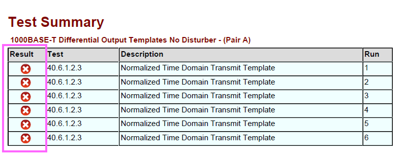
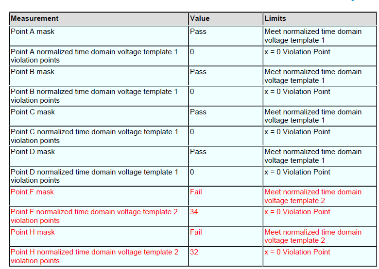
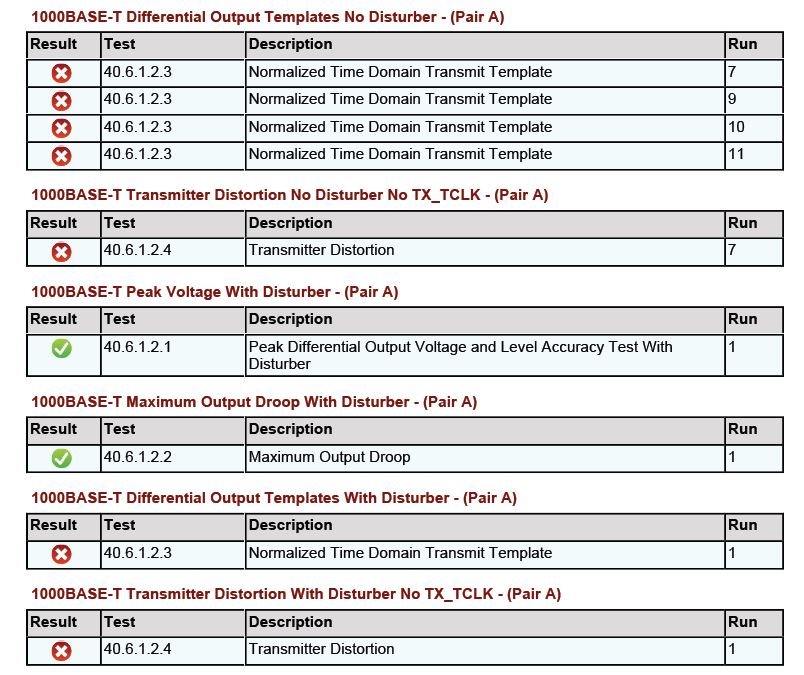
The failing test are listed below.
-Any reasons why those test would fail on the EVM?
-Are there some external condition that might influence the testing?
  • Some feedback I got:
    It seems that a specific script need to be run to initialize the PHY on the EVM prior to run the test.

    The PC side SW tools to run the script are provided at:
    http://www.ti.com/tool/usb-2-mdio
    The script is not publically available and will be provided separatly.

    An MSP430 launch pad is need to interface between PC and DP83867 EVM:
    https://store.ti.com/msp-exp430f5529lp.aspx

    Procedure to follow is detailed in the USB-2-MDIO user's guide document.

    Anthony

  • Thank you for posting the solution, AnBer.
  • Rob,

    Thanks for the comments you provided:
    There is the possibility for coupling between the channels in the transformer which will definitely have an impact on the results if they test with all channels active at a single time.  The xmitter distortion test is the most common victim of crosstalk in the transformer.  The template tests are OK to run with all channels active.


    But it seems that the conformance test is still failing, even after the configuration with the TI scripts.
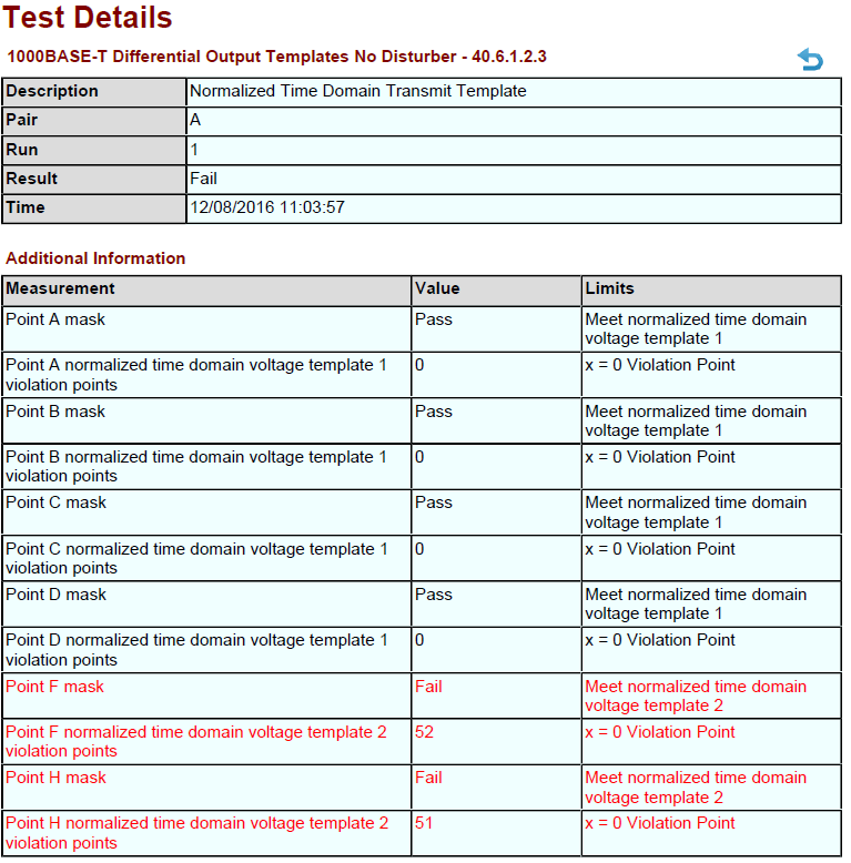
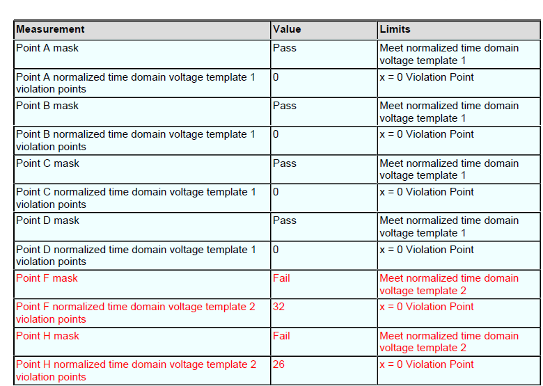
    The portion failing on both TI EVM and custom HW is below:

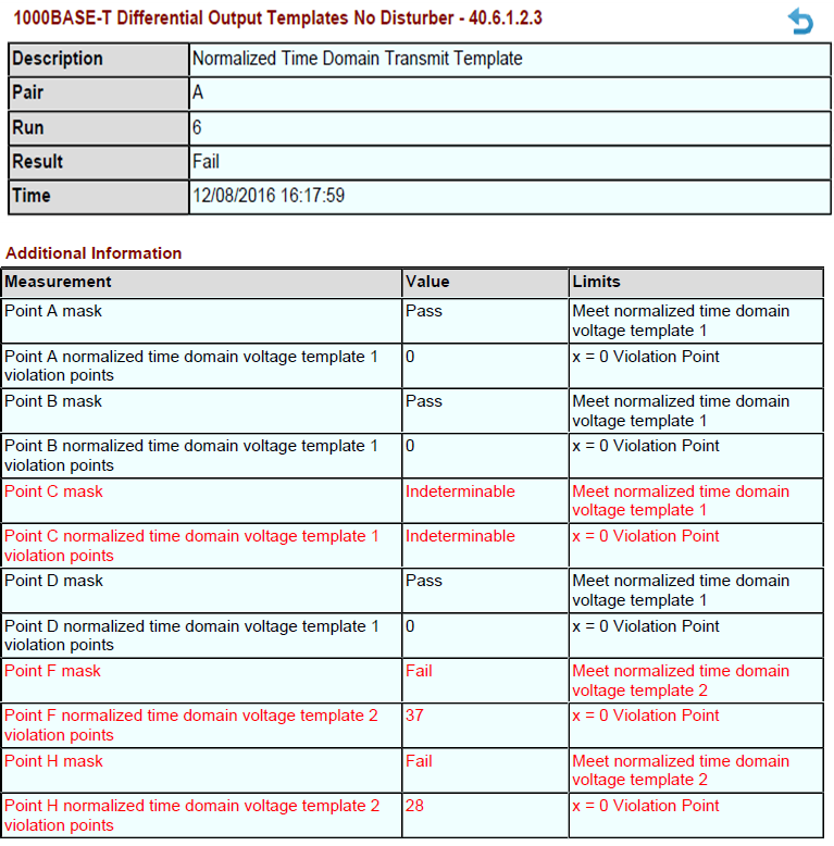
    Yesterday we performed the same test steps on the development board (DEV). The results are added to the same report (see the attachment).

    • Run 1(DUT): only channel A on, undocumented register not written (register 01d5 not set).

    • Run 2(DUT): only channel A on, undocumented register written (register 01d5 set to f508).

    • Run 3(DUT): all channels on (register 0025 set to 0480)

    • Run 4(DEV): only channel A on, undocumented register not written (register 01d5 not set).

    • Run 5(DEV): only channel A on, undocumented register written (register 01d5 set to f508).

    • Run 6(DEV): all channels on (register 0025 set to 0480)

    Development board also fails with suggested testmode settings.


    For RUN 1:


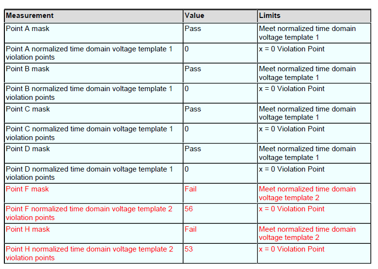
    For RUN 2:


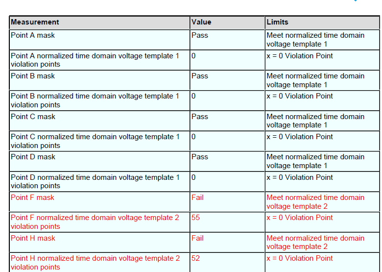
    For RUN 3:


    For RUN 4:


    For RUN 5:


    For RUN 6:


  • Hi Anthony,

    Because there is no improvement seen using the TI EVM and the custom hardware, I believe the register setting is not being made correctly.

    The DP83867 requires an extended register access method for the extended register set.  Please see the DP83867 datasheet titled "Read (No Post Increment) Operation" and verify that the register access method is happening properly.

    Best Regards,

  • Hello Rob,

    To set the DUT in "testmode 1" to perform this measurement you have to be able to write in the extended register set. If you do not set it correctly, no appropriate test signal is coming out. To clarify what is written to perform the measurements I have listed all register access commands below. The write command is interpreted as "mii write DEVICEADDRESS REGISTERADDRESS VALUE". For our DUT the deviceaddress is set to 0. For the development board we connected the mdio bus of the DEV board to our DUT and the device address is set to 2. For the runs 4, 5 and 6 the same set of registers is written, only with the device address changed to 2 (mii write 2 0x00 1140 etc.).

    Write TM1 single channel:
    => mii write 0 0x00 1140 -> 1000Base-T
    => mii write 0 0x10 5008 -> forced MDI
    => mii write 0 0x09 3b00 -> Test mode 1
    => mii write 0 0x0d 001f -> Write extended addressing
    => mii write 0 0x0e 0025 -> Register to write
    => mii write 0 0x0d 401f -> Write extended addressing
    => mii write 0 0x0e 0400 -> Output test mode to channel A
    Measurement Run 1 is performed.

    Write undocumented 0x1d5 register:
    => mii write 0 0x0d 001f -> Write extended addressing
    => mii write 0 0x0e 01d5 -> Register to write
    => mii write 0 0x0d 401f -> Write extended addressing
    => mii write 0 0x0e f508 -> Value
    Measurement Run 2 is performed.

    Write All channels on:
    => mii write 0 0x0d 001f -> Write extended addressing
    => mii write 0 0x0e 0025 -> Register to write
    => mii write 0 0x0d 401f -> Write extended addressing
    => mii write 0 0x0e 0480 -> Output test mode to all channels
    Measurement Run 3 is performed.

    With kind regards,

    Nick Lucas
  • Hi Nick,

    Looking at the below document it seems that you can read back the registers using USB-2-MDIO?
    http://www.ti.com/lit/ug/snlu197/snlu197.pdf
    Can you read the register back to double check it has the correct values?
    Can you try this first on the EVM?

    Hi Rob,
    Are there some specific register that it would make sense to dump to double check the PHY configuration?

    Thanks,

    Anthony

  • Hello Anthony,

    I have did a write followed by a read of the same register address. Device address is 2 which is the EVM, the output results are listed below. Every write is executed successfully:
    Write TM1 single channel write/read
    => mii write 2 0x00 1140
    => mii read 2 0x00
    1140
    => mii write 2 0x10 5008
    => mii read 2 0x10
    5008
    => mii write 2 0x9 3b00
    => mii read 2 0x9
    3B00
    => mii write 2 0x0d 001f
    => mii read 2 0x0d
    001F
    => mii write 2 0x0e 0025
    => mii read 2 0x0e
    0025
    => mii write 2 0x0d 401f
    => mii read 2 0x0d
    401F
    => mii write 2 0x0e 0400
    => mii read 2 0x0e
    0400

    Undocumented register write/read
    => mii write 2 0x0d 001f
    => mii read 2 0x0d
    001F
    => mii write 2 0x0e 01d5
    => mii read 2 0x0e
    01D5
    => mii write 2 0xd 401f
    => mii read 2 0x0d
    401F
    => mii write 2 0xe f508
    => mii read 2 0xe
    F508

    Greetings, Nick Lucas
  • Hi Nick,

    If I understand correctly the compliance test now runs fine.

    It seems that the "How to Configure DP838XX for Ethernet Compliance and Loopback Testing - slna239" document located at
    http://www.ti.com/product/DP83867CS/technicaldocuments has a typo at page 14.
    Refering to your previous post showing the registers setup:
        register 0x0 should be written with 0x0040 instead of 0x1140.

    Best regards,

    Anthony

  • Hi Rob,

    Compliance on 1000BASE-T everything is now working fine but not the 10BASE-Te (energy efficient ethernet) compliance testing.
    Could you pleas help with the following:

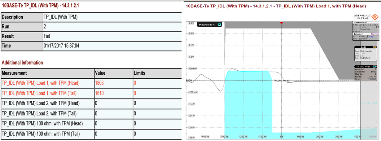
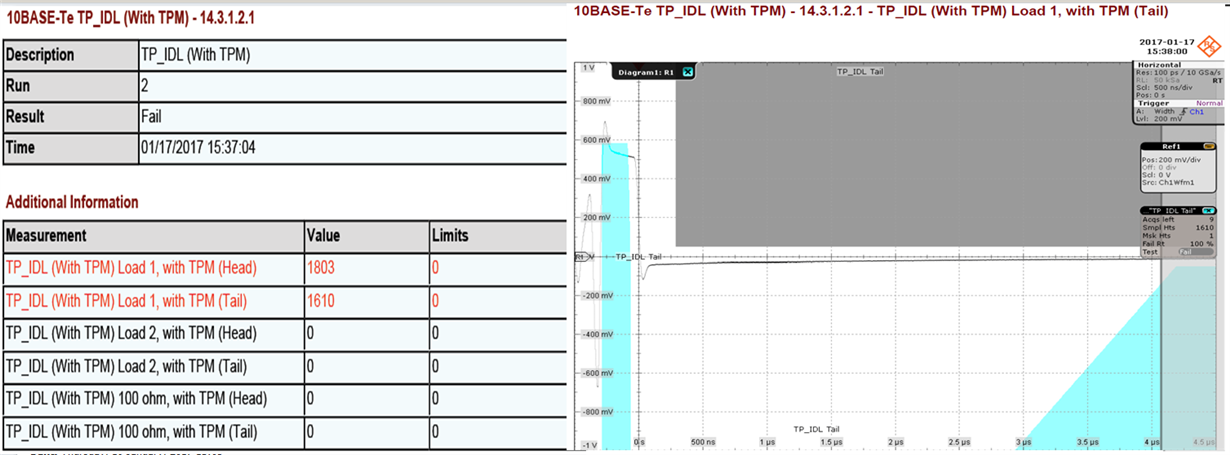
    We were able to perform all 10BASE-Te measurement on the DP83867ISRGZ but the TP_IDL (with TPM) mask continuously failed (see chapter 14.3.1.2.1 in the attached compliance report). According the the standard the mask drawing should be correct. For this test you are not setting the device in a testmode. The PHY is placed in loopback mode, with an external traffic generator we supply the input with pseudo random data and monitor the output signals (Compliance test "with Link partner"). For setting the device in this mode we used the register writes below. Is the ethernet compliance report for 10BASE-Te available for the DP83867ISRGZ PHY? Are there any other configuration options we could try to get the output of the PHY within the mask specifications?

    mii write 0 0x1F 8000 => full reset, including registers

    mii write 0 0x00 0100 => force at 10M

    mii write 0 0x10 5C08 => disable auto MDIX and force link good

    mii write 0 0x16 0020 => set reverse loopback

    mii write 0 0x0D 001F => write extended addressing

    mii write 0 0x0E 00FE => write extended addressing

    mii write 0 0x0D 401F => write extended addressing

    mii write 0 0x0E E720 => set for loopback configuration

    Thanks,

    Anthony

  • Hello Anthony,

    Can you try testing it without the extended register write to 0x00FE?

    -Regards,
    Aniruddha
  • Hello Aniruddha,

    I have tried to do the testing without register write to 0x00FE. No difference, the same mask fail.

    Regards,
    Ton den Bakker.
  • Ton,

    Could you provide a register dump as Nick provided earlier in the this thread (see here)?

    This might help Aniruddha to understand better the condition.

    thanks.

    Anthony

  • Anthony,

    Like Aniruddha asked I left out the last write, so here the dump.

    mii write 0 0x1F 8000 => full reset, including registers
    mii write 0 0x00 0100 => force at 10M
    mii write 0 0x10 5C08 => disable auto MDIX and force link good
    mii write 0 0x16 0020 => set reverse loopback

    Regards,
    Ton.
  • Ton,

    Any progress or news?
    Your comments seems like you do a write. Can you read back the registers just to be sure they are at the expected values?

    Aniruddha,

    What register dump do you need specifically to a more precise idea of the issue? All the registers or just a sub-set of the register?

    Thanks.
    A.

  • Hello Ton,

    We revisited our validation data and on our setup we didn't have to force good link. For the test we would write 0x5008 to 0x10 register. The compliance app note has been updated with the information. The updated app note is at: www.ti.com/.../snla239a.pdf

    Please check with this register setting.

    -Regards,
    Aniruddha
  • Hi Aniruddha,

    For our setup the link has to be forced good (Write 0x5c08 to 0x10). Do you agree that this setting should not have have any impact on the output signal waveform shape? We can continue trying various register settings but this is not relevant to the problem. Could you please perform a measurement of the IDL pulse and send us the result.

    With kind regards,

    Nick Lucas

  • Hi Aniruddha,

    -Is it possible to perform the test requested by Nick?
    -Any input about the effect of forcing the link good (Write 0x5c08 to 0x10)?

    Hi Nick,

    Can you confirm that all the other register settings are as page 13 of snla239a:

    10 Base Link Pulse:

    Reg 0x001F = 0x8000 //reset PHY

    Reg 0x0000 = 0x0100 //programs DUT to 10Base-T/Te Mode

    Reg 0x0010 = 0x5008 //programs DUT to Forced MDI Mode

    10 Base Standard:

    Reg 0x001F = 0x8000 //reset PHY

    Reg 0x0000 = 0x0100 //programs DUT to 10Base-T/Te Mode

    Reg 0x0010 = 0x5008 //programs DUT to Forced MDI Mode

    Reg 0x0016 = 0x0020 //programs DUT to Phy Loop-Back

    Could you please read back the register settings just to be sure?
    Can you confirm that the test setup is comparable to what we show in Fig 4 of snla239a?

    Thanks in advance,

    Anthony

  • Hi Nick,

    I tested TP_IDL compliance with 0x10=0x5C08 and it is passing all three tests (100ohm, load1, and load2). We do not share compliance report on the web so we will arrange to send the results to you offline.

    One question, are you using the 10Base-Te test fixture or 10Base-T test fixture? On our compliance setup the fixtures are separate and 10base-Te needs to be used for DP83867.

    -Regards,

    Aniruddha

  • Hi Aniruddha,

    Thanks for performing and sharing the compliance test results. We are using the 10Base-Te test fixture from R&S. This contains the updated compensation network for measuring the ethernet efficient ethernet (10BASE-Te). Below the writes followed by the register reads we did for performing the measurements:

    => mii write 0 0x1F 8000
    => mii read 0 0x1F
    8000
    => mii write 0 0x0 0100
    => mii read 0 0x0
    0100
    => mii write 0 0x10 5C08
    => mii read 0 0x10
    5C08
    => mii write 0 0x16 0020
    => mii read 0 0x16
    0020

    So there is no difference in output pulse shape when writing the 0x10 to 0x5c08 instead of 0x5008. According to the measurement results the "TP_IDL Load 2 with TMP" is just within specifications (left picture), it leave almost no margin. It would be nice if we could arrange a telephone conference to discuss the results.

    Greetings, Nick

  • Hi Nick,

    How long is the cable that you are using to connect between the DUT and Termination Board?
    Generally, the connection should be as short as possible.

    Kind regards,
    Ross
  • Hello Ross,

    The cable we are using between DUT and Termination Board is the standard 20cm cable which is supplied with the R&S ethernet compliancy test set (RT-ZF2 fixture).

    Greetings, Nick