This thread has been locked.

If you have a related question, please click the "Ask a related question" button in the top right corner. The newly created question will be automatically linked to this question.

DS280DF810: DS280DF810

Part Number: DS280DF810

Hello Team,

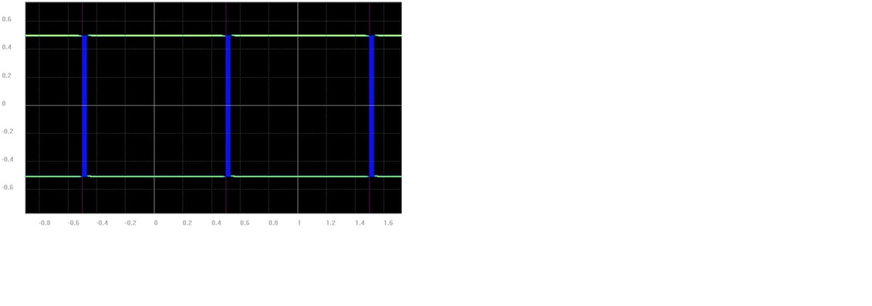
Currently I am doing Signal Integrity Analysis for one of our product by using DS280DF810 Retimer device. So, here I am using Cadence System SI serial link analysis wizard for the serdes simulation. When I am running the channel simulation for Rx nets ( Retimer as receiver), I could able to see the same square wave Rx results without and with considering channel parameters (PCB channels). There is nothing changing in the results. Usually when we are playing with different CTLE and DFE taps settings, we should get different results right? Am I missing something here?, What ever I made some change, I do see the same results. Please get the latest IBIS AMI models, if we need to consider for our simulations. Please find the attached snapshot results for your reference.

Its very critical, because without getting the confirmation on the simulations, we cannot go ahead with our further process. Please help us on this.

Thanks,

Naveenchandra V

  • Hi Naveenchandra,

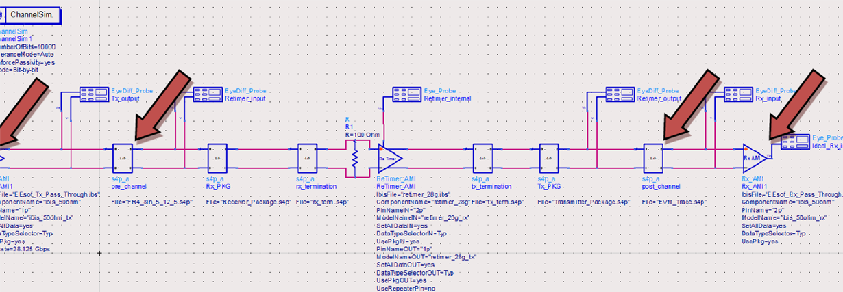
    Do you have a schematic of the simulation that you can share? We'd like to verify that, if the retimer is not used as a receiver and you just use a generic load termination, you will see that there is a difference in the resulting eye diagram as you add PCB trace to the channel between transmitter and receiver.

    If there is still no difference after removing the retimer, then there may be a setup issue with the simulation prior to the retimer.

    Thanks,

    Michael
  • Hello Michael,

    Thank you so much for your reply.

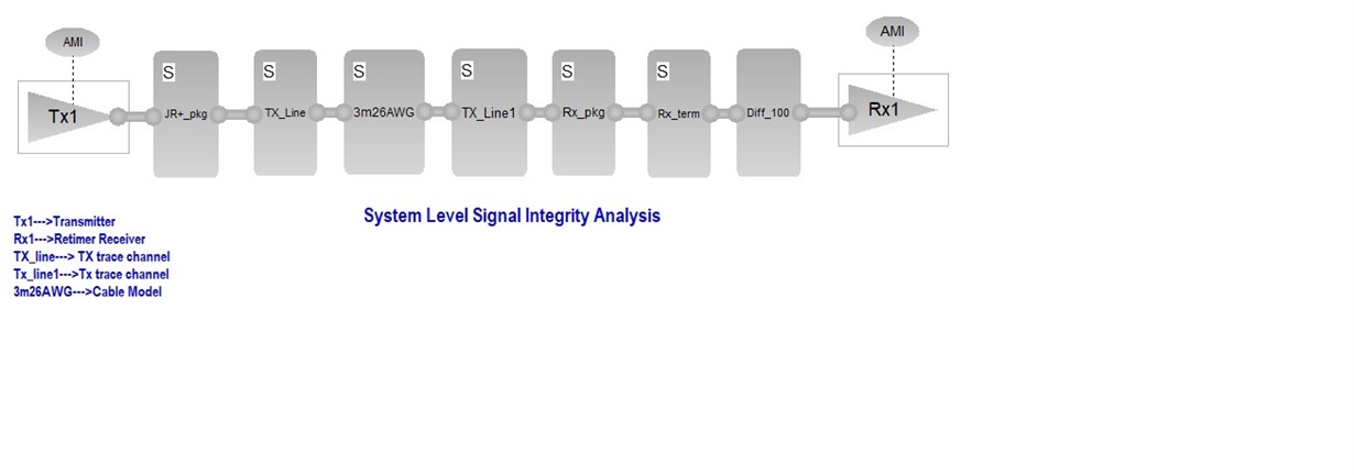
    There is nothing problem with PCB channel, I made it properly. If I use any other devices as receiver, I could able to see the complete eye diagram and difference in the results. But, when I am considering DS280DF810 as a receiver, there is no changes in the results. As I stated above, currently I am usiing cadence System SI wizard for our analysis. Please find the below snapshot for your reference. If I enabled jitter parameters, then I could see slight changes,but not significant changes. What ever results I have capured and shared yesterday, is that correct result? . I have attached schematics for your consideration. Note that, I have not attached tranmitter AMI models, since its confidential. So, you may use any transmitter IBIS-AMI Models for verifications. Please help us on this. I hope my issue would be resolved. 

    Thanks,

    Naveenchandra V

    Serdes25gbps_copy.zip

  • Hi Naveenchandra,

    I will work to replicate your simulation of the DS280DF810 in ADS.  Within your attachment I see the Cable model and a trace model.  Should I use the same trace model for TX_Line and TX_Line1?

    Thanks and Regards,

    Lee

  • Hello Lee,

    Yes, Both Tx_line and Tx_Lines tracemodels are same only. Please take a high priority and get resolve this issue. I would appriciate you. Please let me know whether problem is within the receiver AMI models or are we making any mistakes in the setup?. Note that, I am using 100 Ohm spice model instaed of 100 Ohm differentail terminations near the DS280DF810 device. However, with considering and without consodering 100Ohm at receiver, there is no difference in the results.

    Thanks,

    Naveenchandra V

  • Hi Naveenchandra,

    I'm wondering, when you run these models, can you enable and disable the retiming function of the DS280DF810 so that it is EQ only? If so, we should be able to more easily see the effects of the insertion loss when only EQ is enabled. My thought is that the retiming function of the DS280DF810 model is creating a "perfect" eye output due to the jitter reduction from the CDR block.

    We will still work on trying to recreate your setup, but please note that we will be out on US Thanksgiving holiday from 11/23 to 11/27, so pleas expect delays during this time.

    Regards,

    Michael
  • Hello Michael,

    Yes, I agree your point. The retimer should be work that way. but, In the model, how we can enable or disable the EQ adapatation table. I think, its already enabled. I want to make ensure that, whether we are reciving proper results or not. My concern is that, what ever you made some changes in the IBIS AMI Rx model, no change in the eye output. Also, when we are measuring at input pin of the Retimer device, we could see that, there is no eye opening at all. Signals are ver nasty and worse. However, on the other side, that means from the retimer to end receivers, we are getting around 300mv results and we could able to play some FFE and CTLE and DFE settings. Please create the same setup from your end, and check the compare the results. Also, please share your valuable thoughs and comparison results. 

    Thanks,

    Naveenchandra

  • Hello All,

    I am awaiting for your reply. I hope, This issue will be resolved soon.

    Thanks,

    Naveenchandra

  • Hi Naveenchandra, can you confirm the data rate and test pattern you are using for your simulations?

    Thanks,

    Rodrigo Natal

    HSSC Applications Engineer

  • Hello Redrigo Natal,

    We are using data rate of 25.78Gbps, test pattern PRBS31, Data coding 64/66b coding. Signalling NRZ only.

    Thanks,

    Naveenchandra 

  • Hi Naveenchandra. I believe that there must be some type of setup issue in your simulation environment. TI is able to obtain simulated results that correlate with measurement for different retimer settings. I would suggest for you to go the DS280DF810 product page and click on the link below the "Special Note" to obtain access to the DS280DF810 IBIS AMI model file package. Within those files there is both an IBIS-AMI model quick guide and also a model user's guide. Please review those docs and follow instructions for retimer model setup and configuration.

    www.ti.com/.../DS280DF810

    Cordially,

    Rodrigo Natal

    HSSC App0lications Engineer

  • Hello Rodrigo Natal,

    For your kind information, I have already been received full IBIS AMI file pakages. Also.we read all respective user guide and documents as well. However, we have compared and corelated our results with TI obtained results. There is significant changes in the results. We made proper setup as per the TI recommendations only. However, I have already shared complete channel setup files with you. I would request you to check the results for verifications. It would be very helpful to resolve our issues. Moreover, we are running out of time. So, we cannot go ahead with further process until unless this issues is resolved. So, please check the setup from your end and let me know if any thing is needs to changed.

    Thanks,

    Naveenchandra

  • Hello Team,

    Any update on simulation results?

    Thanks,

    Naveenchandra

  • We are looking into it internally. TI have validated our IBIS-AMI model extensively and confirmed it works, both in our own simulation environment and also at numerous customers. Thus, we are puzzled as to why you are not able to obtain results matching our user guide documents.

  • Hello,

    Look into it internally, share the compared results to naveenchandras@india.tejasnetworks.com . I would appricate you. My concern is that, if we considered 0dB, 35 dB and 45dB insertion loss, there is no change in eye opening. This retimer would support for till 35dB. Thats why I am requesting you. Thanks for understanding. 

    Thanks,

    Naveen

  • Hi Naveen,

    I am not familar with the Cadence System SI tool. Does it support setting up one system simulation with retimer in the middle of the channel, just as we did in the ADS tool?  The repeater pin(connecting the Retimer_Internal probe in the below plot) is expected to observe the pre-sliced signal, which will change as the CTLE/DFE changes.

    Checking the setup as you have, looks like the waveform being checked is already retimed data.

    Regards

    Liang

  • Hello Liang,

    Thank you so much for your reply. Yes, it support setting up one system simulation with retimer in the middle of the channel. earlier I did setup as same as the ADS tool and I capured the results, Results were similar since we were capturing retimed data. So, for time bieng, I have considered till repeater pin (i.e,after DFE and CTLE) and  I am looking waveform being checked is already retimed data. Every thing correct only. What I want from your side is that, you capure the result and compare my results. If the results are overlaying each other, then we are done. My issue would be resolved. I hope now you understood.

    Thanks,

    Naveen

  • Hi Naveen,

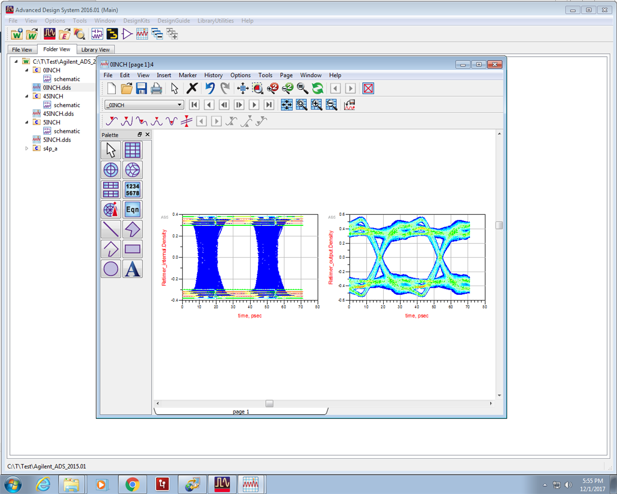
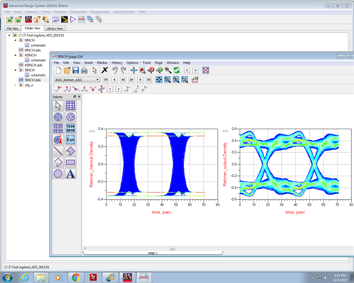
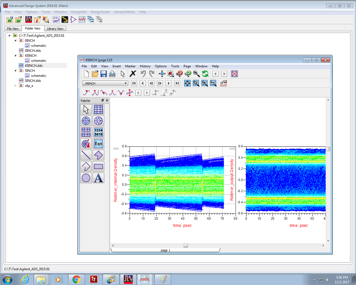
    I tried the simulations using 0 inches FR4, 5 inches FR4, and 45 inches FR4 traces as the pre-channels, based on the ADS example we have in the release package. I oberserved the internal eye(pre-sliced) ,and output signal. Please review the plots below

    Regarding the output signal,  

    a) There are some pre/pst settings and relection noise from the post channel so that we are seeing some overshoot.

    b) It is almost the same between the 0 inches and 5 inches case, when comparing the retimer_output signals.

    c) I was not abe to get open eye for the 45 inches case.

    Regards

    Liang

  • Hello Liang,

    I appricaite your valuable support. Have you captured internal eye(pre-sliced), Is it meeting the eye?, which i have shared earlier. Can you please share that results. Also, regarding output signals, I could able to see the results as you see at output pin of the retimer , No issue in that. Also, Can you please consider my channel and captured the results?, so that we can quickly close this issues. I have already given all the parameters with you. please find below are the details. 

    CAJ5_CBF5_CAI5_CBG5_through.s4p (port 1-->2, 3-->4)

    LB900_23_PN_Tx.s4p (port 1--->3, 2---4) . Any way, you have Retimer IBIS AMI models and respective pkg models.You can consider any transmitter.

    Note: Please don't use any other FR4 materials or parameters, etc.Please share the results at input pin of the Retimer, Internal eye (after the DFE and CTLE) and the outputs signals. we will close the issues.

    Thanks,

    Naveen

  • Hello Liang,

    Any update?. Please let me know.

    Thanks,

    Naveen

  • Hi Naveen, Liang is out today, but should be able to get back to you tomorrow.

  • H Naveen,

    1. The pre-sliced signal is the Retimer_Internal_Density plot, please find them on three plots that i shared last week.

    2. I was able to run some simulations as you requested, and please see my quick summary from the attached word file.

    3. I suggest please keep the total loss of the pre-channel to be less than 35dB @12.8GZ 

    Simulations.docx

    Regards,

    Liang

  • Hello Liang,

    I have gone through the SI comparision results which you have shared last week. I could able to see the internal eye density and its exactly macthing with our captured internal eye density, Only thing is that,eye density is more for your results. This may be due to EDA tool to tool variations. However, I would like to thank you so much for providing lot of technical information on DS280DF810 retimer device. Moreover, I have gone through your quick summary documents. Regadring cable model IL plots, where you have mentioned IL is 21.1db, Yes, It was around 21.1dB, but, recently we have changed this cable to 2m26AWG, now its around 9.8dB. So, our pre-channel total loss will be JR-pkg + 9.8 dB+ 8.4dB + 8.4dB++ TI-pkg = max 29dB and not more than 30db. If you want to check results with upadeted cable model, please find below the attached cable model for your consideration. and let me know your feed back and share your results. Please dont forget it. 

    I appriciate you for your great support. I will close the issues. We will go ahead with further process on the same. 

    Thanks,

    NExaMax_Reduced.zipaveen