This thread has been locked.

If you have a related question, please click the "Ask a related question" button in the top right corner. The newly created question will be automatically linked to this question.

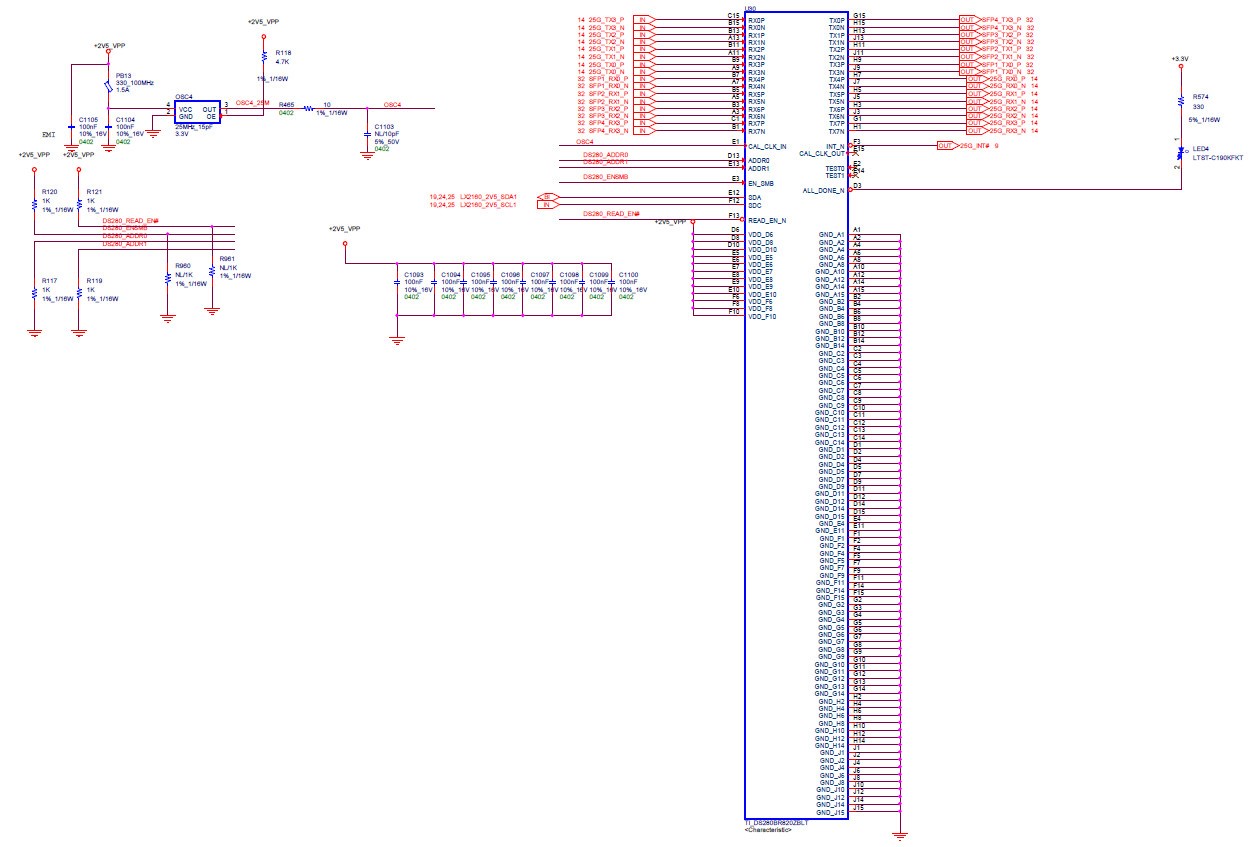
DS280BR820: default setting of DS280BR820 is 25G or 10G

Part Number: DS280BR820
Other Parts Discussed in Thread: DS280DF810, DS250DF810

Hello :

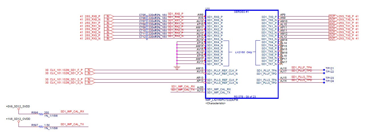
We  have a project that use DS280BR820 with NXP cpu  LX2160.

The operating speed is 25G  , does we need use I2C command  to change the setting.

I am confuse to the setting of DS280BR820 

thanks

edwin

  • Hi Edwin,

    The DS280BR820 is a linear equalizer, it will operate at either datarate.  The equalization settings will need to account for the link characteristics.  Longer channels with more attenuation will benefit from higher equalization settings.

    Do you have additional information about the link attenuation and topology?

    Regards,

    Lee

  • Hi lee

    We design with low lose material ( -1.92/db per inch)

    the length of CPU to CDR is around 2 inch , CDR to SPF+ also around 2 inch.

    Until now the link still can't be linked up . Dose DS280BR820 have any register can be monitored by I2C bus to help us clarify what is happen.


    thanks

    edwin
  • Hi Edwin,

    Are you using the default register settings?
    Please send a file with all the register values if you have made changes.

    Regards,
    Lee
  • Hi Lee

    we use default setting

    thanks

    edwin

  • HI lee

    I have dump the register as below
    0000: 01 00 00 00 01 00 00 40 00 38 02 00 91 00 00 00 .......@.8......
    0010: 00 00 00 00 00 00 00 00 00 00 00 00 00 00 00 00 ................
    0020: 00 00 00 00 00 00 00 00 00 00 00 00 00 00 00 00 ................
    0030: 00 00 00 00 00 00 00 00 00 00 00 00 00 00 00 00 ................
    0040: 00 00 00 00 00 00 00 00 00 00 00 00 00 00 00 00 ................
    0050: 00 00 00 00 00 00 00 00 00 00 00 00 00 00 00 00 ................
    0060: 00 00 00 00 00 00 00 00 00 00 00 00 00 00 00 00 ................
    0070: 00 00 00 00 00 00 00 00 00 00 00 00 00 00 00 00 ................
    0080: 00 00 00 00 00 00 00 00 00 00 00 00 00 00 00 00 ................
    0090: 00 00 00 00 00 00 00 00 00 00 00 00 00 00 00 00 ................
    00a0: 00 00 00 00 00 00 00 00 00 00 00 00 00 00 00 00 ................
    00b0: 00 00 00 00 00 00 00 00 00 00 00 00 00 00 00 00 ................
    000c: 91 00 00 00 00 00 00 00 00 00 00 00 00 00 00 00 ................
    00d0: 00 00 00 00 00 00 00 00 00 00 00 00 00 00 00 00 ................
    00e0: 00 00 00 00 00 00 00 00 00 00 00 00 00 00 00 0c ................
    00f0: 00 40 00 00 00 00 00 00 00 00 00 00 00 00 03 10 .@..............

    thanks

    edwin
  • Hi lee


    i2c mw 18 0xfc 0x80
    => i2c mw 18 0xff 0x01
    => i2c md 18 0x00
    0000: 00 80 00 80 90 04 c0 20 54 00 30 1a 40 40 00 00

    the channel 7 and Channel 0 can detect RX input but it still not link

    Does  DS280BR820 have loop back mode 

    for example  Channel 0 RX connect to Channel 7 TX for debug

    thanks

    edwin

  • Hi Edwin,

    Since you are relatively close to the CPU I would recommend to reduce the CTLE gain in the DS280BR820 equalizer.

    Here are two adjustments to the channel register settings.

    0x03:  Change from 0x80 to 0xC0    /* this gives the CTLE maximum bandwidth

    0x04:  Change from 0x90 to 0x91     /* this lowers the CTLE gain using a partial bypass

    Regards,

    Lee

  • HI lee

    Does RX and TX use the same setting??

    10G can linkup but 25G still fail

    if I operation at 25G does I need  change  CTLE setting?

    thanks

    edwin

  • Hi Edwin,

    What type of signal is coming into the Rx side?  What is the topology and approximate loss at 12.5 GHz for 25G datarate operation?

    The settings which work at 25G will also work at 10G. 

    Regards,

    Lee

  • dear Lee

    25G-Aui  at Rx side ,lose is  around  -4db  at 12.5Ghz (2 inch  and -1.91 per inch).

    10G is work but 25 not

    thanks

    edwin

  • Hi Edwin,

    I worked to emulate your application.

    Tx (800mV) ->  -2 dB -> BR820(1) ->  -4 dB  ->  BR820(2)  ->  scope

    I get pretty good eye openings using the following settings.  The optimal settings will change significantly if any Tx equalization is enabled in the NXP CPU.

    DS280BR820 (1)

    i2c mw 18 0xfc 0x80  (CH7)
    => i2c mw 18 0xff 0x01
    => i2c md 18 0x00
    0000: 00 80 00 80 B1 04 40 20 54 00 30 1a 40 40 00 00

    DS280BR820 (2)

    i2c mw 18 0xfc 0x01 (CH0)
    => i2c mw 18 0xff 0x01
    => i2c md 18 0x00
    0000: 00 80 00 91 B1 04 40 20 54 00 30 1a 40 40 00 00

    The changes use a partial bypass on both equalizers.  I increased the equalization a few small steps in BR820 (2) and set the EQ gain to "high" in both devices.

    The VOD in both equalizers is set to level 1 (range 0-3)

  • Dear Lee.

    Thanks for kindly help.

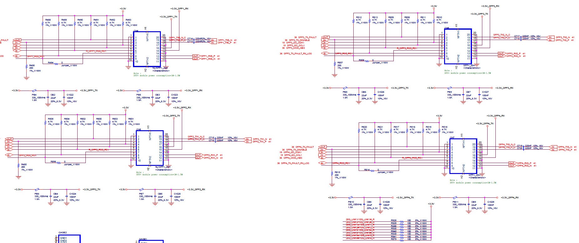
    Can you provide DS280BR820 all setting for 25G application about below signal chain. Please also reference schematic on attached file.

    If you need any more information or your suggestion please kindly let us know. Thanks~

    Signal chain

    CPU =>  2 inch(-4 dB) => BR820(CH 0~3) =>  2 inch(-4 dB)  =>  SPF+

    SPF+ =>  2 inch(-4 dB) => BR820(CH 4~7) =>  2 inch(-4 dB)  =>  CPU

  • Hi AJ,

    I have the same setup here

    Generator =>  2 inch(-4 dB) => BR820(CH 0~3) =>  2 inch(-4 dB)  =>  SPF+

    SPF+ =>  2 inch(-4 dB) => BR820(CH 4~7) =>  2 inch(-4 dB)  =>  Scope

    For CH 0-3

    My settings are as follows

    EQ stage 1: Bypass

    EQ stage 2: 1 (Range 0-7)

    Bandwidth: 2 (Range 0-3)

    DC Gain: High (Range Low-High)

    For CH 4-7

    My settings are as follows

    EQ stage 1: Bypass

    EQ stage 2: 4 (Range 0-7)

    Bandwidth: 2 (Range 0-3)

    DC Gain: High (Range Low-High)

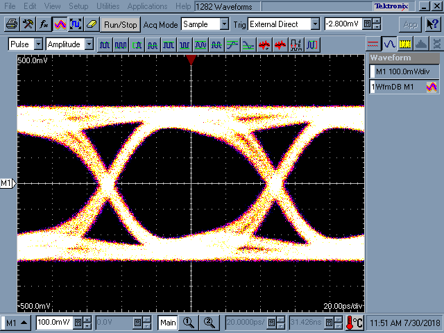
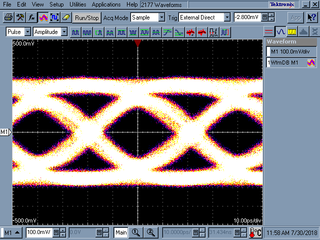
    I have attached waveforms at the scope measurement point.

    10Gbps

    25G

    Regards,

    Lee

  • Dear Lee

    Thanks for kindly help~

    The result of today's verification is that only signal is detected. But not work yet.

    Please kindly help us to check below setting is anything mistake. Thansk~

    Write to channel 0

    => i2c mw 18 0xfc 0x01

    => i2c mw 18 0xff 0x01

    => i2c mw 18 0x00 0x04

    => i2c mw 18 0x06 0x12

    => i2c mw 18 0x04 0xb1

    => i2c mw 18 0x03 0x88

    => i2c mw 18 0x06 0x00


    Write to channel 7

    => i2c mw 18 0xfc 0x80

    => i2c mw 18 0xff 0x01

    => i2c mw 18 0x00 0x04

    => i2c mw 18 0x06 0x12

    => i2c mw 18 0x04 0xb1

    => i2c mw 18 0x03 0xa0

    => i2c mw 18 0x06 0x00


    Read back setting

    => i2c mw 18 0xfc 0x01

    => i2c mw 18 0xff 0x01

    => i2c md 18 0x00

    0000: 00 80 00 88 b1 04 00 20 54 00 30 1a 40 40 00 00    ....... T.0.@@..

    => i2c mw 18 0xfc 0x80

    => i2c mw 18 0xff 0x01

    => i2c md 18 0x00

    0000: 00 80 00 a0 b1 04 00 20 54 00 30 1a 40 40 00 00    ....... T.0.@@.

  • Hi AJ,

    The value in register 0x06 should be 0x40 to achieve VOD = 1

    You seem to be writing to the same register twice in the sequence for each channel.

    Regards,

    Lee

  • Dear Lee.

    Good day.

    In your previous suggestion only EQ stage 2 is different between CH 0-3 and CH 4-7.

    Based on your suggestion. We sett CH 0-3 0x03 is 88 and CH 4-7 0x03 is a0.

    Please let me know if there are any errors. Thanks for kindly help~

  • ear Lee.

    Good day.

    We test the DS280BR820 eye diagram on this project. But the result doesn't look good.

    Please kindly reference on attached file. Please give us some suggestions. Also, will Retimer products be better?

    Like DS250DF810 / DS280DF810. Thanks for kindly help~

    3386.DS280BR820 Eye Diagram 20180801-TW.PPT

  • Hi,

    Based on the waveforms you have more than 4 dB of loss.  The EQ1=0, EQ2=0 setting is approximately 10dB of gain.

    Where is your measurement point for the waveforms?

    There are decent eye openings in several of the graphics.  

    The retimers would help to reduce jitter, but the waveform on page 6 looks good enough as a receiver input.

    Regards,

    Lee 

  • Hi Lee,
    Tks your suggestion !
    Waveform is from SFP+ connector with 32GHz scope.
    We find linear mode couldn't open eye evidently but limit mode more easy to open .

    Do you prefer limit mode? Any side effect?

    Tks!
  • Using limiting mode will make it easier to achieve a large vertical eye opening for oscilloscope viewing.

    The linear mode requires that the 25G receiver has some built in CTLE and DFE capability to provide additional boost to open up the eye as well.

    The side effect of limiting mode is that it will often disrupt the link training process.

    Regards,

    Lee

  • Dear Lee.

    Good day.

    Based on the results of our test. Can you provide the settings for CH 0~3 and CH 4~7?

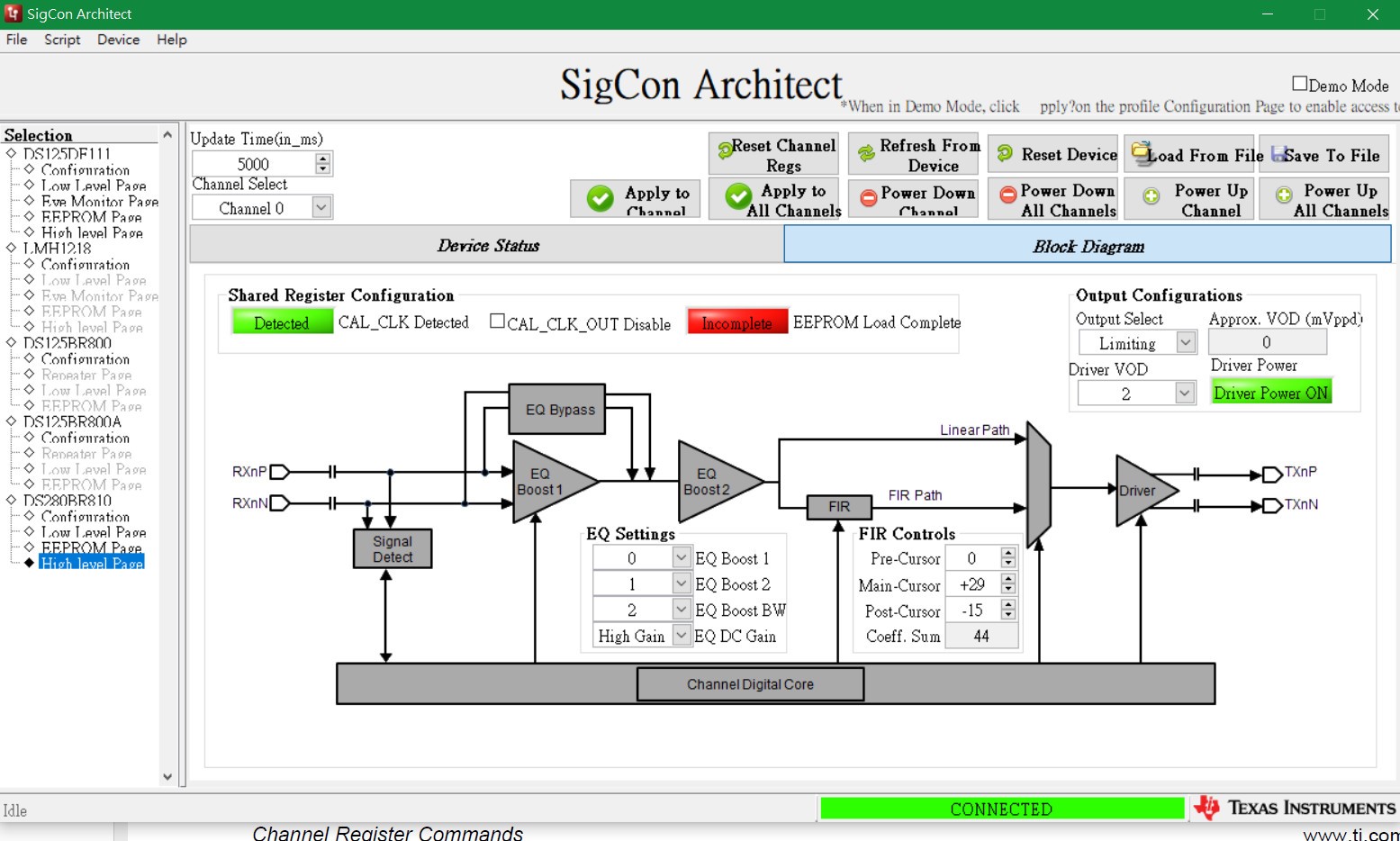
    Would you recommend us to use FIR control? If possible, Please kindly provide your suggestions like below photo.

  • continued discussion via email
    - Lee