This thread has been locked.

If you have a related question, please click the "Ask a related question" button in the top right corner. The newly created question will be automatically linked to this question.

TCA6416A: Turn on DC motor 12V 50W nearly, erases the configuration registers

Part Number: TCA6416A
Other Parts Discussed in Thread: TCA6416

Hello,

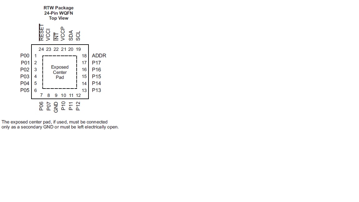
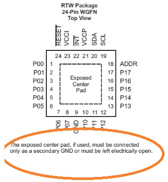
I have a problem with this I2C expander TCA6416ARTWR. everything is fine, but when I turn on a DC 12V 50W motor near to the PCB the registers of configuration are deleted. (without I2C traffic).

The sequence is this:

- turn on the electronic

- I set the I2C: reg 4, 5, 6 and 7 (00, 3F, 00, 3F)

- I read the configuration from this registers and they are fine (00, 3F, 00, 3F)
- no more traficc on the I2C bus

- turn on motor

- turn off motor

- I read the configuration register and they have been reiniciated (00, 00, FF, FF)


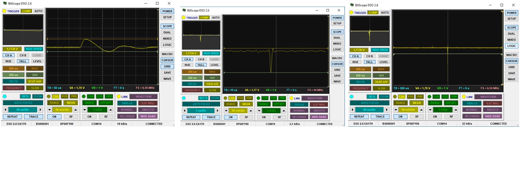
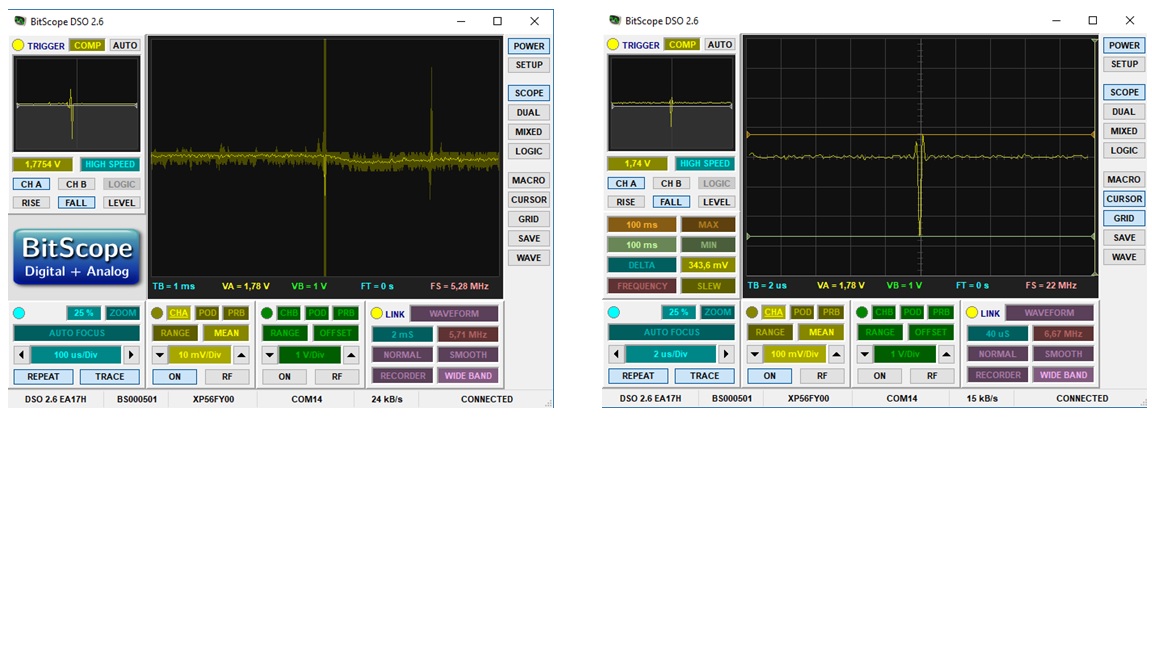
I don`t see Vcc noise and reset signal is 10K pull-up near to chip

I guess it is a noise problem, but this one seems too susceptive. what reason can to reiniciate the configuration? How can I improve the desing? Can you help my?

  • Hello Serio,

    There are one of two things that can reset the TCA6416A, either Vcc is lowered past it's reset voltage or the RESET pin is seeing a voltage that toggle the register reset.   I would add a capacitor at your reset pin first.  See if that fixes your problem. 

    Make sure your scope is not bandwidth limited and look at both Vcc and RESET pins during the motor startup and shutdown.  Try and make low noise measurements, hopefully you are using short ground probes and make sure the probes have a high enough bandwidth to capture the event. 

    My guess is that adding a decoupling cap on RESET will fix it.  You might have to play with the values.  It would be nice to capture the event that way we could get more information.  Please send waveforms if this doesn't fix it.

    -Francis Houde

  • Hello Francis,

    Thanks for you quick answer!

    I have been doing probes as you say me.

    My scope is bad (it is a USB scope) 20MHz 12Bit and my probes are worse ... (6MHz).. What features do you thik that I need?

    With this devices, I see:

    reset pin:

    I think that this es little variation

    With a 10uF in reset pin (the problem is smaller but if I move a lot of the motor the registers are deleted. the signal with 10uF:

    Finally, I disconect the reset pin and conect it to 1,8V near directly. The problem is similar to that of 10uF in reset pin. Then, I also connect 10uF in paralel and the problem is similar. signals:

    What do you think? I need a new scope...I guess....?

  • Hello Francis,

    The Exposed Center Pad isn't connected to GND. It is connected to a small electrically open area . Is it correct?

    Thanks

  • Hey Sergio,

    The exposed center pad is used for heat dissipation purposes so I don't believe this will cause any issues.

    -Bobby
  • Hello Sergio,

    Your scope probably isn't fast enough (wide enough bandwidth) to capture you noise event.  Also, what is your ground reference for the probe and also the ground reference for the device. 

    It looks like you are using Altium.  Can you send me the packaged project so I can review the layout.  If the grounding and the location of the decoupling caps isn't done correctly then you might have issues like this. 

    Send files to francis.houde@ti.com

    Let me know where you placed the 10uF decoupling cap on RESET pin.  Also, did you try the decoupling capacitor on Vcc.  Take a look at that during transients too.

    Sorry for the late response.  I will be better about it.  I say Bobby responded but I didn't realize that your other questions hadn't be answered as well.

    -Francis Houde

  • Hello Francis,

    OK, I send you the Email

    Thank you very much

  • Hello Francis,
    Have you received the Email?
    greetings
  • Hello Sergio,
    Did you get my email and did that capacitor on Vccp fix the problem? Let us know.
    -Francis Houde
  • Hello Francis,
    Have you received the Email? I sent it to you last week
    greetings

    It's this:

    Hello Francis,

    U2 only with 22uF ceramic capacitor in RESET pin is OK. I can’t make it fail. Without this capacitor, if turn on the motor then U2 is restarted the 90% of the times. Without this capacitor and with a 100nF capacitor in VCCP, U2 is restarted too.

    The capacitor in RESET pin seems the solution. However I will add a capacitor in VCCP too in the redesign.


    Now I have only the same problem in U13 when I turn ON/OFF the motor. Then I connect the 22uF capacitor in RESET PIN then it improvement (of 90% of times to 10% of times). It’s less frequently that without the capacitor, but is a big problem too. In U13, VCCP and VCCI is the same connection. In the design, a 100nF capacitor is connect to this connection (C42).Then VCCP and VCCI have the same capacitor.  I’ve put a 22uF capacitor in parallel to C42 too but it don’t improvement.

    Can I do anything more?

    Do I connect the thermal pad to GND? Are you sure? Sorry, but I'm afraid to break it. The datasheet say:

    Thank you very much

    Greetings

  • Hi Sergio,

    Francis has been on vacation lately but should be back in the office next week.

    I'm glad to hear you have had some success in addressing the problem. To help improve things further, one thing that may make sense is to introduce some series resistance on the reset line in addition to the capacitor. This could help reduce the currents that flow when noise is induced via the cycling of your motor.

    Regarding the thermal pad, I can confirm that it is OK to connect it to ground. It just should not be connected to any other active nets on the PCB.

    Regards,
    Max
  • Hello Max and Francis,

    thanks for the reply

    I have attached the thermal pad to negative. but it does not improve. The series resistance in the reset line is very difficult to put into the prototype now. I will put the resistors in series in the next design.

    Do you think I can do something else to try? Any advice on the next redesign? any change in the routing?

    thank you very much

  • Hello Sergio,
    I think you need to at least have place holders for decoupling capacitors at a few different locations. Also, any IO pin dealing with that reset pin should have a good ground underneath it and have decoupling capacitors footprints at both the TCA6416 and at the master.  Also make sure decoupling caps for Vccp is close to part and has good ground connection. Make sure pullup resistor path is minimized too, put is next to TCA6416.  Remember you are looking for loops that can pickup noise as antennas.  When you get it done send it to me to review, I am always willing to look at the layout.
    -Francis Houde