This thread has been locked.

If you have a related question, please click the "Ask a related question" button in the top right corner. The newly created question will be automatically linked to this question.

DS90UB913A-Q1: Which is the default mode either 10-bit or 12-bit?

Part Number: DS90UB913A-Q1
Other Parts Discussed in Thread: DS90UB914A-Q1

[ DS90UB913A-Q1 ] Which is the default mode either 10-bit or 12-bit?

Hi,

Which is the default mode of DS90UB913A-Q1 either 10-bit or 12-bit after power-up?

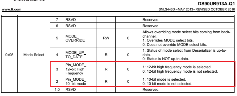
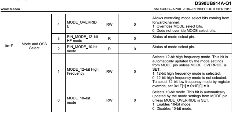
I know the mode 10-bit or 12-bit of DS90UB913A-Q1 is set by DS90UB914A-Q1 through back-channel. And, from the 0x05 register of DS90UB9i13A-Q1, it seems that both modes are NOT selected. Please help to make sure the default mode just after power-up.


Thanks,
Ken


<Related Post>:

DS90UB914A-Q1: MODE Settling Time
e2e.ti.com/.../2540410

  • Ken,
    The deserializer should automatically configure the serializer to correct mode based on the MODE pin setting and RMODE resistor value.
    On the serializer do you have the MODE_OVERRIDE bit enabled or disabled?
  • Hi Palaniappan,

    Yes, I know that the serializer should be set automatically.
    My question is that what is the default mode of UB913A (12-bit or 10-bit) before transferring 914A's setting to serializer?

    Thanks,
    Ken

  • Ken,
    If the MODE_OVERRIDE bit is not set, it should be configured through the back channel from the deserializer.
  • Palaniappan,

    Thanks. You don't have information of default mode of DS90UB913A-Q1, correct?
    What I guess from datasheet is that the default mode would be 12-bit low frequency mode. Because the default value of register bits are not set such way.


    Thanks,
    Ken

  • Hi Pal,

    Let me ask one more thing.

    Is there any register on UB914A which indicates the configured mode (10-bit or 12-bit) of UB913A?

    As my understanding, UB914A's 0x1F indicates the mode of UB914A itself.


    I know that the mode of UB913A is configured automatically once lock is achieved between UB913A and UB914A.
    Also, the mode of UB913A can be checked from UB914A with UB913A's 0x05 through remote access.


    I would like to know whether any resistor on UB914A which indicate the mode of UB913A directly.

    Thanks,
    Ken

  • Check this other thread on a similar topic that may have some relevant information for you:
    e2e.ti.com/.../265062
  • Hi Pal,

    Thank you for your support, but the thread, you suggested, does not answer my questions.
    Here I summarize my question again, can you please help me to support my customer?


    <Q1>:
    Is there any register on UB914A which indicates the configured mode (10-bit or 12-bit) of UB913A?

    I expect the answer is either yes or no. If yes and you can share the details of that register, it's appreciated.

    <Q2>:

    Would you please let me know the minimum number of Deserializer Data Lock Time (tddlt)?

    No guarantee required, just reference and/or rough number are fine.


    <Q3>:

    In order to improve the receiver eye integrity, my customer tries to implement the sequence which turn-on and off the backchannel communication with 0x02[2].
    i.e. the back channel is enabled only when it's required.

    Would you please let me know the minimum duration which requires for UB913A and UB914A to communicate and configure correctly?
    Again, no guarantee required...


    Sorry for asking you many questions. But we are struggling to find out the way to resolve the issue occurred at OEM.
    Actually, it's really close to the final call, that's why we don't have chances to change the hardware and need to find out a solution with software.

    Thanks,
    Ken

  • Ken,
    For new questions please create separate threads using "ask a related question" feature. It will be easier to manage the threads if you limit to 1 thread per question instead of adding new ones to an existing thread.

    Q1: No, you need to read register 0x05 on the serializer.
    Q2: We do not have min values, only typical and max. Max is more important as it covers across conditions.
    Q3: Not sure why they would want to switch on and off unless they are multiplexing two cameras or inputs. This is not a validated use case so we wouldn't have timing info to provide. By the way, the register should be 0x01[2] for BC enable/disable.