This thread has been locked.

If you have a related question, please click the "Ask a related question" button in the top right corner. The newly created question will be automatically linked to this question.

SN6501: isolated +/-15Vout rail from 5Vin.

Part Number: SN6501

Hello,

I would like to design low noise isolated +/-15V rail from 5V input.

Design Requirement :

   Vin : 4.5 - 5.5V

   Vout : -15V 90mA / +15V 40mA

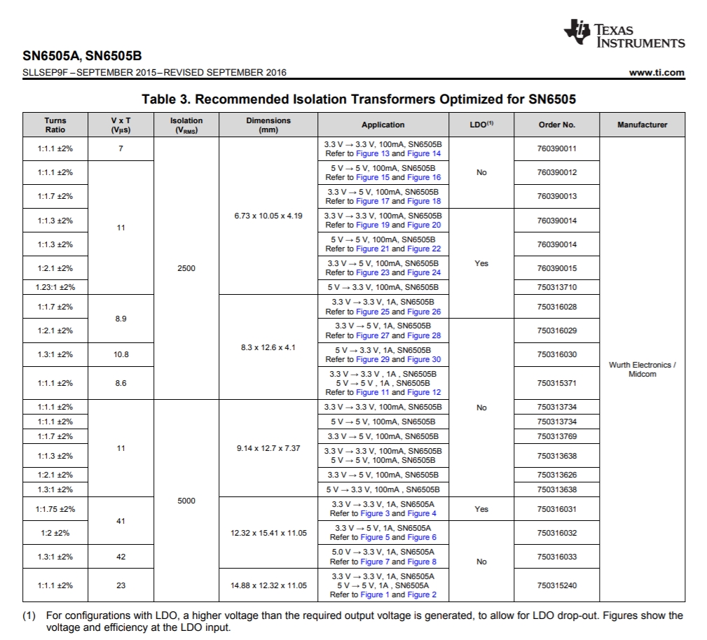
Since I can't find any transformer for SN6505 from Mouser, Digikey and Farnell,

I decided to use two SN6501 with two transformers.

Do you see any problem with this design?

Can you recommend any transformer for SN6505 with more than 1:1.7 turns ratio and higher current capacity that I can purchase from Mouser, Digikey or Farnell?

Thank you.

EH

  • Hi EH,

    Welcome to TI E2E forums and thanks for posting your question online :)

    For this situation, the best solution (smallest area) would be to use a single SN6505 solution (1A power budget) + a single 1:3 transformer.
    Yes, you are correct that 1:3 transformers are not listed . I am out of the office today due to local holiday, but will follow-up in the next day or two to see if there are any other part numbers I can dig up for you.

    The good news is that this is very common, so you can go to any transformer vendor of your choice and they will be more than happy to build a 1:3 quick prototype for you per your needs. We have a design guide in the datasheet to help in this process, and of course we can also help you for this!

    The limitation with 6501 and multiple transformers is the power budget limit of 6501 (only 350mA) at 5V supply. So you will be operating at the edge of the power budget. For example, 350mA at 5V, becomes 98mA at 16V on the secondary side.

    [4.5V worst case primary; you need 16V at secodnary [0.7V for diode drop + 0.3V for optional LDO]. So turns ratio required = 16/4.5 = 3.55
    So the primary current budget becomes 350mA /3.55 = 98mA ]

    Gaining two transformers together in series, although possible in theory, will be tricky to implement.
    If you put them in parallel (one for +15V rail and another for -15Vrail), then you will still need a 1:3 transformer.


    So the best case is still one SN6505 + one 1:3 (custom) transformer. I will follow-up with a part number as mentioned above. If i can\t find a part, then I recommend going the custom design route.

    Hope this helps!
    Thanks,
    Abhi
  • Thanks for posting the diagram EH, even with this option, you will need a 1:3.5 or 1:3 turns ratio. Will follow-up as mentioned !

    Regards,
    Abhi
  • Thank you Abhi
    I will look forward your transformer recommendations!
  • In the schematic I uploaded, I used 1:1.7 transformer with voltage doubler rectifier. Isn't it feasible option if we can't find 1:3 transformer in production?

    Thank you.
  • Hi EH,

    Thank you for your patience. I found the following transformer designs with 1:3.5 turns ratios.

    1) 750316818 

    2) 750316769

    You can use these designs/part numbers as examples. Hope this helps!

    Also, just the rectifier circuit wouldn't give you voltage doubling,  you would need another capacitor in conjunction with the diodes and a slightly different topology for that.  However, since you have the right turns ratio, this should now become easier.

    Thanks,

    Abhi

  • Hi Abhi,

    Many thanks for transformer recommendations.

    Unfortunately the problem is I can't buy recommended 1:3 transformer from anywhere.

    Do you have other transformer recommendations form other suppliers which is in mass production?

    If not, I would like to stuck with two sn6501 with two transformers since I can buy MIDCOM 1:1.7 transformer everywhere. - one for positive rail, the other for negative rail.

    One thing that I would like you to check my schematic once again, I didn't use center tap so output voltage will be 1.7*2*5 = 17V as it is described in the sn6501 datasheet.

  • Hi EH,

    You are welcome. 

    I see, I don't have any other  transformer recommendations at the moment, sorry. You can ask your preferred vendor to make a prototype if you like, but that will take a few weeks before you can test and then approve it for production.

    Your other option is also OK. It is not the smallest solution, but yes it can be considered. Good point on not using the center-tap - that does make a difference and it gives you the full swing . So you have 2*Vcc swing in the primary windings (D1 to D2 )and the turns ratio is "n", so you will get 2*Vcc *n across the two end points of the secondary windings.

    You  will get 17V swing in typical case (5V input), but you have to account for Diode drop and LDO drop out voltage before the final output. Also, you will have = 2 * 4.5 * 1.7 = 15.3V worst case swing on  the secondary windings  when Vin = 4.5V , so we need to be careful here. so it is better to pick a transformer with a higher turns ratio. (maybe closer to 1:2).

    Shown below is a list of transformers in the SN6505 datasheet (ok to use with 6501 also). Within this list, I'd recommend using the 750316032 device with a 1:2 turns ratio. This gives you margin to cover for supply variation on the primary side,  and also has big V x T product ( = 41V-us) to allow for bigger voltage swing, and also gives you reinforced isolation capabilities.

    Hope this helps, 

    Abhi

  • Thank you Abhi,

    Now I have confidence with my design.
    Thank you.