This thread has been locked.

If you have a related question, please click the "Ask a related question" button in the top right corner. The newly created question will be automatically linked to this question.

DP83848K: MDIO signal can not match with datasheet showed in figure 6 -2

Part Number: DP83848K

Dears,

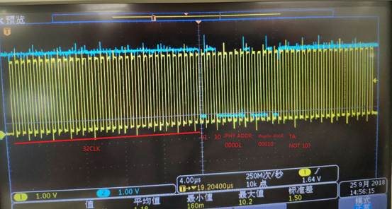
   I have a problem when I want to read PHY register(02H,Identifier Register 1) through MDIO with RMII mode. MDC clock is 16.67MHz.

the Figure 6-2 shows that 

It means "Z0" during the first bit of Turnaround, but I receive "11" during my testing showed as below,

please give me a hand for some reason maybe, thanks a lot.

  • Hi,

    Is it working for you in MII mode ?

    Regards,
    Geet
  • HI,

          I am the Hardware Engineer who design this circuit.It's me to ask Mr gong to consult this question .I use  the RMII mode in the circuit.

  • Hi:

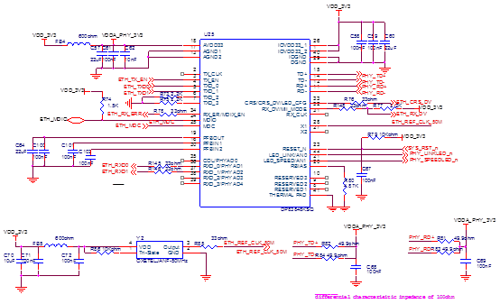
           The top figure is the circuit.I have the follow question:

    1) The phy address input  is designed to floated as shown in the above figure .Does this design can be reliably ? Now I'm not sure the real phy address in DP83848 is my  expect value 01.

    2)How much is the Voltage on the pin  PFBOUT of DP83848 when the circuit normal?

         I am debugging the circuit.so hoping to see your reply as sogn as possible,thanks very much!

  • Hi,

    Can you try reading at Phy address 0 to 31 ?

    On PFBOUT, you shall see 1.8V.

    Regards,
    Geet
  • Hi,
    My soft engineer have try this method,but not yet. But I can try again if should.
    Note: Having test the circuit , I can sure the follows: the supply voltage is normal;the reset signal is normal; the Power on Sequence is normal。 Now i want to ask two questions:
    1、I want to confirm if the phy address is true ,we can read data from the phy register? for example ,if the 50M clk is out of the specifications or MDIX_EN is diable when reset state,or the AN0 and AN1 is not 11 state ,and so on? in other words,I mean reading data Successfully from regiser only with the MDC , the right phy address and the time sequence between mdc and mdio?
    2、when I connect the Rj45 on the circuit with the switchboard,the LED status on the switchboard is not right.But when i use a development board to do this ,the LED status is right. So ,I debut my circuit have something wrong .Can you help me to check my circuit ?I have found mdix_en,AN0,AN1 pins status is not my expect state when power up reset process .
    Hoping to see your reply.Thanks very much .
  • HI,
    Adding a quesiton and descriptiving a test result,which can help to find the problem:
    After powerup, when connect with another PHY RJ45,I cann't test the FAST lINK PULSE. Why? The FAST lINK PULSE should have no connection with the phy setting,for example the MDIX_EN,AN0\AN1 state when reset,and MII or RMII mode.
    Another questioon,I want to sure the defaulte state of Auto-Negotiation is enable,no matter with the state of AN0\ANI pin are sampled during reset process?
  • Can you check RX_CLK clocking on the line ? Want to ensure Phy is powered up properly ?

    Regards,
    geet
  • HI,all,

              I am so sorry.I found the problem.I Forgot to connect the pfbout pin to the pfbin. Thanks everyone who help me to find the problem.

       Best Regards