This thread has been locked.

If you have a related question, please click the "Ask a related question" button in the top right corner. The newly created question will be automatically linked to this question.

HD3SS3220: USB 3.0 C device to USB 3.0 device on the same PCA

Part Number: HD3SS3220

Hi 

I'd like to use the HD3SS3220 to interface a USB C device connector to a USB 3.0 device on the same PCA

I am concerned about getting the connector / device interconnections correct e.g. should it be TX-TX,  RX-RX (not the differential pairs) 

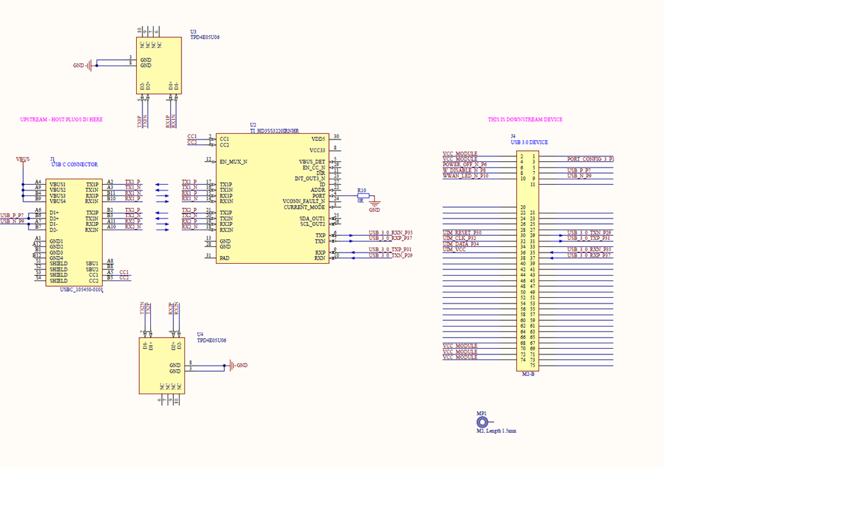
The following is an attempt at modelling this

[UPSTREAM?] <----->[DOWNSTREAM?]

[USB_3.x_HOST][USB C]----standardCable-->[USBC]  ---pcbTx1or2DifPair--> [ RX1or2 HD3SS3220] [ TX HD3SS3220] ---pcbTxDifPair -->[USB_3.xDEVICE_RX]

[USB_3.x_HOST][USB C]<---standardCable---[USBC]  <--pcbRx1or2DifPair-- [ TX1or2 HD3SS3220] [ RX HD3SS3220]<--pcbRxDifPair---[USB_3.xDEVICE_TX]

I'm pretty certain this is incorrect - any ideas how this should be connected

Many thanks

John

  • John

    The best place to start is to take a look at our EVM design and use it as a reference for your design.

    For DFP Dongle Design: www.ti.com/.../sllu237.pdf.
    For UFP Dongle Design: www.ti.com/.../sllu241.pdf.

    You can send me your schematic in *.pdf format after you finish your design and I can review the connection for you.

    Thanks
    David
  • Hi David

    Many thanks - the pdf links didn't work - there are links on the following page - luckily this time I looked the UFP schematic downloaded the DFP didn't.

    The following is my guess at the connections - the USB 3.0 DEVICE directtions are correct apart from that I can't figure out how to check the rest

    Thanks

    John

  • John

    Please refer to Figure 12 of the HD3SS3220 datasheet for the connection of the remaining signals.

    The connection between Type C Connector and HD3SS3220 is correct. TXP needs to be connected to the transmitter output of the downstream device and RXP needs to be connected to the receiver input of the downstream input. Currently the arrow does not seem to indicate this to be the case.

    You also need AC coupling caps on USB SuperSpeed signals, you can also refer to Figure 12 of the datasheet.

    Thanks
    David
  • Hi David

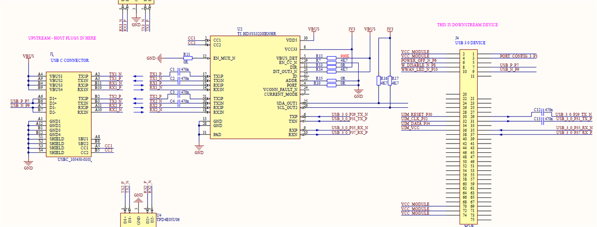
    Thanks for the feedback - the demo board schematic has the CAPs in the RX1/2 lines which contradicts the Schematic Figure 12 of the datasheet. I'm hoping the following is now correct but I don't really understand the mux TX/RX direction documentation in the datasheet :)

    Many thanks

    John

  • John

    Here is my schematic review comment:

    Do you have power decoupling caps on VCC33 and VDD5?

    Recommend 100nF & 1uF on VCC33 and single 47uF and 1uF on VDD5

    C1, C21, C3, and C4 need to be 100nF

    C12, C13 not needed

    R13 needs to be 200k

    ID Pull high through 200k to 5V

    VCONN_FAULT_N pull high through 200k to 5V

    ADDR is pulled to GND, are you planning to use I2C?

    R14 200K

    Thanks
    David
  • Hi David

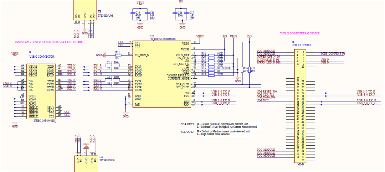
    Many thanks for all the feedback - I don't understand why TX1 & 2 are outputs to the USB C socket as the board is an upstream facing device?

    Well spotted with the I2C configuration - in the design it is better for us to use the OUT1 and OUT2 pins as HW outputs to indicate the host current capability 

    I'm hoping the schematic is correct now

    Thanks

    John

  • John

    USB Spec defines the orientation of Type C connector. TX is defined as transmitter output while RX is defined as receiver input.

    Otherwise schematic looks good.

    Thanks
    David
  • Hi David

    Many thanks

    Just to remind myself in the future - the USB C cable connects TX-RX and RX-TX (described here "USB Type-C Specification Release 1.3.pdf") this is why the TX is always TX at the C connector

    Thanks

    John