This thread has been locked.

If you have a related question, please click the "Ask a related question" button in the top right corner. The newly created question will be automatically linked to this question.

TCA8418: TCA8418 Concurrent key presses losing one of the presses

Part Number: TCA8418

I'm having a problem when I press more than one key at a time.  Pressing any 1 key is detected perfectly, always.  If I press 2, or 3, or more keys, if they all occur at the same time (as close as my hands are pressing them concurrently) sometimes 1 or more won't register going down.  The same is true when I release the keys as well.

While my matrix does have 1n4148 diodes, I am able to reduce my design to just enabling 3 keys to even see this behavior, they have taken over completely column 4, 5 and 6.

So to be sure, and disable all the other row/column, I put this:

writeI2C8(FD_PANEL,0x1D,0x00); //SET ROWS PART OF KEYSCAN (R0-R4)
writeI2C8(FD_PANEL,0x1E,0x00); //SET ROWS PART OF KEYSCAN (C0-C3, C7)
writeI2C8(FD_PANEL,0x1F,0x00); //SET ROWS PART OF KEYSCAN (C8-C9)
writeI2C8(FD_PANEL,0x20,0x00); // ROW5 GPIO INTO FIFO


writeI2C8(FD_PANEL,0x21,0x70); // COL456 GPIO INTO FIFO

I've scoped the signals on 4 5 and 6 and they look fantastic.  Not seeing any capacitance droop or excessive ringing.

The only thing I know that is not 100% correct is ROW 6 and 7 are floating because they are not being used in any configuration.  But given the rows are open anyways if no button is down, I didn't think that would cause any problems.

I'm just not sure what else to check.  I have 2 boards built up and both behave exactly the same.

  • When I say take over for 4, 5 and 6, each column goes to a button which has ground on the other side.
  • As a test, I rewrote the code to brute-force scan all inputs (so I am doing what the internal hardware is supposed to do). I set the rows as inputs, set the columns as outputs, drive one column at a time, and I also read the GPIO that I am using direct to a switch connected to ground.

    This works PERFECTLY. No matter how many keys I hit, how fast, I've not lost a single up or down with my polling.

    So at this point, I really don't know what the problem is with the internal keyscan. I hate giving up CPU cycles to do this manual scanning. That said, I just wanted to verify that I didn't see any bounce or lag issues there when hitting fast or multiple keys.
  • Hey Richard,

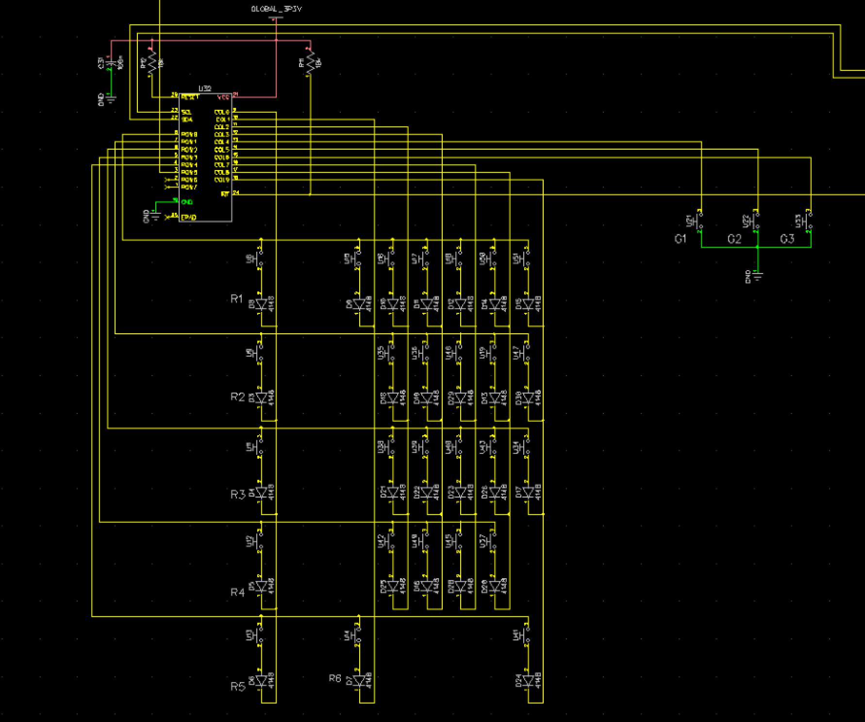
    Can you provide a schematic for me to review? A block diagram of your keypad matrix with the switching diodes would be useful to me as well.

    How long do you press the keys for? Are you doing this by hand or using a function generator and a FET to model a key press in the first post you've made?

    Are you able to place o-scope probes on the rows of the buttons you are pressing? This may help us with debugging.

    Thanks,
    -Bobby
  • Bobby,

    This was all done with momentary press chips in circuit.  I've attached the circuit as laid out on the PCB.  SDA/SCL coming from an ARM processor.  100nF between power and ground.  10k pull-up on reset and INT.

    That said, to reduce the complexity to a more simple problem, I just set up the TCA8418 to just listen to the columns with the switches labelled G1, G2 and G3.  This way, only those three were being watched and only those three were told to insert their values into the key buffer.

    Key presses were done by hand.  So if I push down (and held) 2 buttons at the same time, in some cases, one of them would not be detected.

    If I then waited any amount of time then released both at the exact same time, many times one of them will not get detected as leaving the engaged state.  

    It's as if when they both happen at the same time, it cannot see one of them in some cases.

    If the circuit is just watching for changes on those columns assigned to G1, G2 and G3, I am unclear how it could not see the changes.

    (row 5 goes off to another grounded switch and is used as a GPIO, but in the simple case, I ignored it and just used the 3 columns)

    Thanks!
    Rick

  • Hey Richard,

    Just to confirm, are you using this device in keypad mode when you are using just the columns?

    Thanks,
    -Bobby

    EDIT: meaning did you configure the column3-5 to be GPIOs or part of the KP matrix. register 0x1E (KP_GPIO2)

    From your first post it seems the device thinks that column 3-5 are part of the keypad matrix because you have them set as KP with your 0x00h.

  • What I did to eliminate any questions about diodes was setup just eveything to gpio but then set those 3 to put their changes in the keyboard buffer to limit the test. In those tests only those 3 inputs are allowed to go to ground when pressing those 3 buttons. That said they behave exactly the same as the scanned matrix. 2 keys on gpio presses at same time by hand, one missed.
  • Hey Richard,

    If columns are set to be part of the keypad matrix (through KP_GPIO2 register) then what the columns actually do is go into a GND state when the device is in idle mode. When the device detects a falling edge (on a row input) it enters into scanning mode and then sets all the columns to be HI-Z while it strobes each column to GND for a short amount of time to try to detect which row actually went low.

    These events are recorded in register 0x04 with a FIFO depth of 10 bytes. Now this is for the keypad mode.

    "writeI2C8(FD_PANEL,0x1E,0x00); //SET ROWS PART OF KEYSCAN (C0-C3, C7)"
    If you write 0x00 into this then all the columns from 0 to 7 will be a GPIO and not part of the keypad.

    So you are using the device now as a GPIO where the default setting is an INPUT defined by GPIO_DIR2. The default GPIO_PULL2 register then have your Columns 3-5 as an internal pull up to 100k into Vcc. I believe in this mode the column will then function as a 'row' in active scan mode.

    "writeI2C8(FD_PANEL,0x21,0x70); // COL456 GPIO INTO FIFO"
    This is meant to be a read register which indicates if a column is part of a FIFO event.
    You should be reading the event register to actually read the FIFO (0x04 for event A register).

    Does reading this register until it is empty still show that only one press event has happened?

    Thanks,
    -Bobby
  • Yep, that's what happens when I press 2 keys at the same time, but not every time, it's intermittent (or likely I am not hitting them at exactly the same time every time since I am just pushing with two fingers).

    If I press each of the buttons by themselves and release, I see in 0x04 both down and up as I read them out.  If I even do say A down B down A up B up slowly I see them all.  If I do just A as fast as I can possibly hit the button, I never miss a down and up sequence from the FIFO.

    However, if I press them down at the same time (as exact as I can) and I look what comes out of the FIFO, I get one of them down and not the other.  Not ever time, let's say like 50% of the time it misses one.

    I keep pulling from the FIFO until it returns 0.

    I even just kept pulling from the FIFO and just printing out when it was not zero,  just to see if it was in there, but somehow was after a zero returned.

    It's like somehow, when I hit both buttons at the same time, one is masking the other.  (Let's forget about keyscan mode for now and just focus on those 3 as GPIO that I told it record their changes in the FIFO).

    When I hooked up a scope to the switching to see what the bounce looked like, very clean edges.  

    Just doesn't seem like a lot of other settings to try changing.

    Rick

  • Hey Richard,

    I ordered some EVMs for this device to be shipped to me. I will try to see if I can reproduce what you are seeing as well.

    I do have quite a bit to do this week so I may not be able to get the EVM set up immediately when it does arrive but I will try (likely this Friday).

    One thing you can try doing is adding an external pull up resistor on your columns (about 10k or so) to Vcc and repeating your multi button press test. Let me know if adding the resistors changes the results.

    Thanks,

    -Bobby

  • Hello Bobby,

    For columns C4, C5 and C6 I tied a 12k (all I had) resistor to VCC (3.3V) and then reran the test on just those 3 buttons (each column had it's own 12k tied to VCC).  No change in performance.  Pressing multiple buttons still ends up causing events to be missed in the FIFO.

    Rick

  • Hey Rick,

    Just to verify that you wrote to the internal registers correctly. can you do a register read of 0x1E and 0x21? I would like to see this on the I2C lines (SDA/SCL) in a scope shot of the read transaction.

    I also have one of our system engineers doing some testing with the TCA8418, he agreed to try to recreate the problem you are seeing as I am a little overloaded at the moment. I believe he will look into this tomorrow so I will let you know what he finds by end of day tomorrow.

    Thanks,

    -Bobby

  • Hey Rick,

    The engineer was not able to get to trying to recreate this today and said he should be able to do it tomorrow.

    Sorry for the inconvenience,
    -Bobby
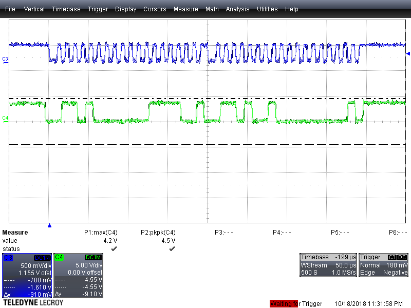
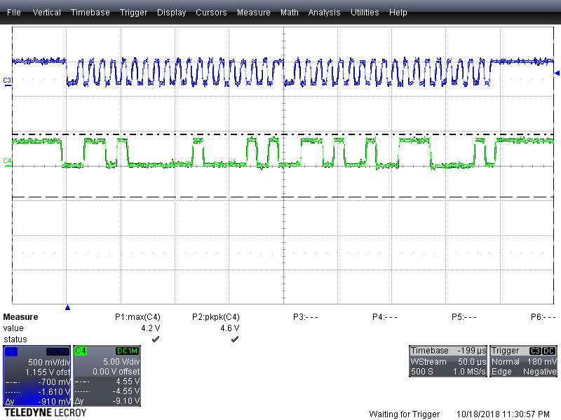
  • No problem at all.  Here are some scope captures.  Remember that right now I am setup to just look at C4, C5 and C6 coming through the FIFO, so when I read the values (using i2cget) I do get 0x1E=0x00 and 0x21=0x70.  I did this over and over to make sure I never got a wrong result, and I did not.  Which is consistent with my manual scan results.  Note that I have tried I2C at 400k and 1M (currently at) just to make sure it wasn't communication issues.

  • Hello Richard,

    I'm the one helping Bobby with this one. I've got the TCA8418e EVM set up. Since I cannot do your exact setup, I modeled it at closely as I can. I shorted COL0, COL1, and COL2 together so that any single press would trigger all 3 lines at exactly the same time. I have all rows setup as GPIO outputs, outputting low, so they're tied to ground. I have all columns setup to write to the event FIFO. I only press 1 button at a time, so it effectively looks like 3 columns were pressed at exactly the same time.

    When I press a button, I see in the event fifo that all 3 buttons were registered/detected. I also check the column status register and see that all 3 buttons are read as a low. When I release, I see the same thing, all 3 are detected without issues.

    Could you try shorting your column buttons together so that a single press will guarantee all 3 are pressed at same time and see if it changes your failure mechanism? I'd be curious if doing that made you miss key presses or releases 100% of the time.

    Do you have interrupts enabled for the column buttons? What about the debounce circuitry, is it written to 1 (debounce disable) or 0 (debounce enable)?

  • When I soldered a wire across columns 4, 5 and 6 (and verified the connections were working), when I trigger any 1 button of the buttons, C4 and C6 register button down and up, but C5 shows nothing.  Without the wire, C5 works as long as I press one button at a time.

    For the other buttons still hooked up, if I hit them at the same time, sometimes what happens is C5 is registered along with some other button, but then C4 and C6 don't show up.  And of course in that scenario, buttons get stuck.

    No matter how quick I tap ( or long press) C4 and C6 ALWAYS detect proper with C5 never showing anything.

    Debounce is on (but I tried it both ways)

       writeI2C8(FD_PANEL,0x01,0x11);   //CFG
    
       writeI2C8(FD_PANEL,0x1D,0x1F);   //SET ROWS PART OF KEYSCAN (R0-R4) 
       writeI2C8(FD_PANEL,0x1E,0x8F);   //SET ROWS PART OF KEYSCAN (C0-C3, C7)
       writeI2C8(FD_PANEL,0x1F,0x03);   //SET ROWS PART OF KEYSCAN (C8-C9)
    
       writeI2C8(FD_PANEL,0x20,0x20);   // ROW5 GPIO INTO FIFO
       writeI2C8(FD_PANEL,0x21,0x70);   // COL456 GPIO INTO FIFO
       
       //writeI2C8(FD_PANEL,0x01,0x95);   //CONFIGURATION SETTINGS
       writeI2C8(FD_PANEL,0x0E,0x00);   //SET ULOCK TIMERS TO ZERO SO IT IS DISABLED
       writeI2C8(FD_PANEL,0x0F,0x00);   //SET ULOCK KEY1 TO ZERO FOR DISABLE
       writeI2C8(FD_PANEL,0x10,0x00);   //SET LOCK TIMERS TO ZERO SO IT IS DISABLED
       
       writeI2C8(FD_PANEL,0x02,0xFF);   //RESET ALL INTERRUPTS

    I've tried many different combinations of settings, this is what I was using for this test for setting things up.

    This was the last routine I was using to check the contents:

    int ScanPanel(char* keyArray) {
       uint8_t int_stat = readI2C8(FD_PANEL,0x02);
       if(int_stat&0x01){
          //keyboard event
          uint8_t key_lck_ec = readI2C8(FD_PANEL,0x03);
          uint8_t event_count = 0xf&key_lck_ec;
          if(event_count>0){
             uint8_t key_event = readI2C8(FD_PANEL,0x04);
             while(key_event != 0 ){
                uint8_t key_state = key_event&0x80?1:0;
                uint8_t key_val   = key_event&0x7F;
                key_event = readI2C8(FD_PANEL,0x04);
                if(key_state){
                   keyArray[key_val]=1;
                } else {
                   keyArray[key_val]=0;
                }
    
             }
          }
       }   
       writeI2C8(FD_PANEL,0x02,0x01);
    }

  • Thanks for the feedback. This has me wondering if it's column and row specific.

    I am going to wire up col 4, 5, and 6 and use your port configuration exactly to see if that changes the behavior.

    Sounds like once you soldered them together, you get this failure to detect 100% of the time, correct? So at least it's consistent now.

  • I've copied your code/configuration and am trying this on COL4, 5, and 6. I always get all 3 keys to show up, whether a press or a release.

    You mentioned you see this on multiple boards? Do you see this on every board? Or just some?

    I have one more idea I'm going to try to try and replicate your issue (using the same package you have), to see if there's any difference there.
  • To answer your first question, yes, it is always consistent now, C5 never show up when I have all 3 buttons wired together.

    Pertaining to your second question, we built up 2 prototypes of a product we are trying to ship by the end of the year.  Both are behaving exactly the same.  One thought I had is could I have possibly received a bad batch of chips.  Seemed unlikely, but that's all I could think.  Both boards are behaving identically. 

    My internal 2 layers are power and ground planes, so I'd think power would not be a problem.  Power is being supplied through a MCP1700T3302 driving that plane.  When I hit keys, I do not see any droop or anything happening.

  • Richard,

    Just giving an update. We don't have any boards in house for the RTW package (loaned them and never got them back). I was trying to modify another board but I was unsuccessful. We have ordered new boards to solder down a RTW.

    I am starting to suspect that there may be something with the TCA8418 specifically. There are 2 variants of this device. The TCA8418 and TCA8418E. The E is an enhanced device which has improved ESD protection as well as the erratas in the TCA8418 are fixed.

    I've been doing my testing on the E variant to try to see if it's a software configuration issue. We won't have the board for a few days unfortunately. Please let us know if you discover anything new that might help us replicate the issue.

  • Let me see if I can locate an E part as well.

    For now, here is the part I used from Mouser:

    595-TCA8418RTWR                        
    MFG Part No: TCA8418RTWR
    Texas Instruments Low-Vltg 16B I2C &  /  Interface - Specialised
    US HTS:8542390001 ECCN:EAR99 COO:MY
    
  • I didn't realize that is a BGA only package, which isn't going to work on this board.
  • Yeah, that's why I'm having issues trying to test the qfn. Only have the bga boards currently.

    They have identical register set and configuration, the E variant is just improved performance but only comes in a BGA package.
  • Hey Rick,

    We received our QFN to DIP adapter boards yesterday and I submitted them to be soldered by our lab technicians today. I expect them to be done end of today or tomorrow afternoon.

    I'll let you know when we start testing them and if we find the issue you are seeing on our device.

    Thanks,
    -Bobby
  • Hey Rick,

    I got our TCA8418 (non E revision) and began testing today.

    I just ran my program using Column 4 5 and 6 tied together to an NFET drain. The source was tied to GND. I was able to detect all 3 pins going low and going high when I pulled the NFET gate from low to high and back to low.

    Below is my serial monitor of what I program via I2C and what I read as well.

    Originally we thought the E version and non E version were different and the non E could have a potential bug with multiple buttons pressed at the same time when set as an input. But this doesn't seem to be the case here.

    This leads me to believe the issue may be related to the layout/soldering/code?

    We may need to back step and take a look at the layout first and move forward from there. Maybe check to see if the soldered connections are good.

    -Bobby