This thread has been locked.

If you have a related question, please click the "Ask a related question" button in the top right corner. The newly created question will be automatically linked to this question.

TMDS171: I2c read/write issue - TMDS181

Part Number: TMDS171
Other Parts Discussed in Thread: TMDS141, TMDS181, TUSB3410

Hi all

I'm using TMDS171 between HDMI connetor and FPGA,sink side.I have met just the same problem as the link shown below.The frequency of I2C clk is 100KHz

That thread has been locked without resolved.

https://e2e.ti.com/support/interface/f/138/t/680883?tisearch=e2e-sitesearch&keymatch=tmds181

Anyone could help?

Thanks!

  • Hi,

    Yes, this issue was resolved through internal email. The customer was not writing the register address before attempting to read it back. Can you provide more information on what the exact issue you are seeing is?

    Thanks,
    JMMN
  • Hi,

    I use TMDS171 between HDMI connector and FPGA.

    The problem is that FPGA can capture 720P60 vedio data successfully,but cannot capture 1080P60 vedio data,the 1080P60 data capatred is incorrectly.

    The i2c read/write issue  has been resolved ,and the configure is shown as below.but the problem remains

     <i2c_bitrate khz="100"/>

    ======No Lane Swap

    ======No Polarity Swap

    ======Signal detect disabled

    ======Power down disabled

    ======HPD Automatic power down enabled

    ======Local I2C data rate 100k

    */

    write_TMDS171(0x09,0x02);//

    /*

    ======Tx impedance 150 to 300 ohms

    ======DDC data rate 100k

    ======

    ======

    */

    write_TMDS171(0x0B,0x08);//150~300

    //write_TMDS171(0x0B,0x00);//no terminal

    /*

    ======Vswing DATA defined by Rvsadj

    ======Vswing CLK defined by DataRate

    ======2dB de-emphasis

    */

    //write_TMDS171(0x0C,0x01);//Vswing DATA defined by Rvsadj;Vswing CLK defined by DataRate;pre-emphasis:2dB

    write_TMDS171(0x0C,0x6D);//VSWING_DATA Increase by 18;VSWING_CLK Increase by 18%;pre-emphasis:2dB

    /*

    ======Data Lane EQ 6.5dB

    ======Clock Lane EQ 3dB

    ======

    */

    //write_TMDS171(0x0D,0x15);//6.5dB 3dB

    //write_TMDS171(0x0D,0x25);//10.5dB 3dB

    write_TMDS171(0x0D,0x3A);//16.5dB 3dB

    /*

    ======Sink application

    ======HPD_SNK gate enable

    ======Fixed EQ

    ======EQ Enabled

    ======Apply RxTx changes(Asser this at the end)

    ======Automatic redriver to retimer crossover at 1.0 Gbps

    */

    //write_TMDS171(0x0A,0x95);//Automatic redriver to retimer crossover at 1.0 Gbps

    write_TMDS171(0x0A,0x94);//fixed redriver mode

    //write_TMDS171(0x0A,0x97);//fixed retimer mode

    //toggle PD_EN bit

    write_TMDS171(0x09,0x5);//enter Power down mode

    //read_TMDS171(0x00);

    write_TMDS171(0x09,0x02);//exit Power down mode

    //read_TMDS171(0x00);

    while(1)

    {

    read_TMDS171(0x00);

    cnt++;

    }

  • What is the status of the registers during the test (0x09h - 0x0Dh)? I would recommend trying automatic retimer to redriver mode and adaptive EQ.

    Thanks,
    JMMN
  • Hi,JMMN


    write_TMDS171(0x0B,0x08);//150~300

    write_TMDS171(0x0C,0x01);//Vswing DATA defined by Rvsadj;Vswing CLK defined by DataRate;pre-emphasis:2dB

    write_TMDS171(0x0D,0x35);//14dB 3dB

    write_TMDS171(0x0A,0xB5);//Automatic redriver to retimer crossover at 1.0 Gbps;Adaptive EQ

    write_TMDS171(0x09,0xA);//enter Power down mode

    write_TMDS171(0x09,0x02);//exit Power down mode

    the reg value is shown below:

    reg0x09:0x02

    reg0x0A:0xB1

    reg0x0B:0x08

    reg0x0C:0x01

    reg0x0D:0x35

    Thanks!

  • Hi
    I removed TMDS171 from one board,and I connected the input pins and the corresponding output pins with jumper,then FPGA can capture the 1080P60 data

    I changed to pinstrap mode:
    I2C_EN/PIN:L
    SIG_EN:NC
    VSadj:6.98K to GND
    TX_TERM_CTL:NC
    SWAP/POL:NC

    and I tried to change the state of EQ_SEL & PRE_SEL:
    EQ_SEL PRE_SEL
    NC NC
    NC L
    H NC
    H L
    L NC
    L L
    but the issue remained in the above 6 situations

  • Ok a few questions: you are setting a fixed EQ value in register 0x0Dh, but then setting the TMDS device to adaptive EQ mode via register 0x0Ah, what's the intended use case? Also, after making register changes, the apply rxtx bit needs to be set in register 0x0Ah...is this being set? Since you are using the TMDS device with a FPGA, can the FPGA handle standard TMDS signals or does it require AC coupled inputs?
  • Hi,JMMN 

    Thank you for your help

    /*********************about FPGA input****************************/ 

    My board was designed refered to Digilent Genesys video FPGA(Xilinx,XC7K325T)  EVM board.

    The Digilent Genesys EVM board uses TMDS141 between FPGA and HDMI input connector,DC coupled,just as my case.

    Since TMDS141 has a limited working temperature,I choose TMDS171,and the FPGA I used was the same as the Digilent Genesys EVM board.

      /******************* about EQ mode******************************/

    Both the fixed EQ mode and adaptive EQ mode had been tested,the problem remained the same

     /*********************about RXTX apply****************************/ 

    RXTX changing was applied by writing 0xB5 or 0x95 to reg0A

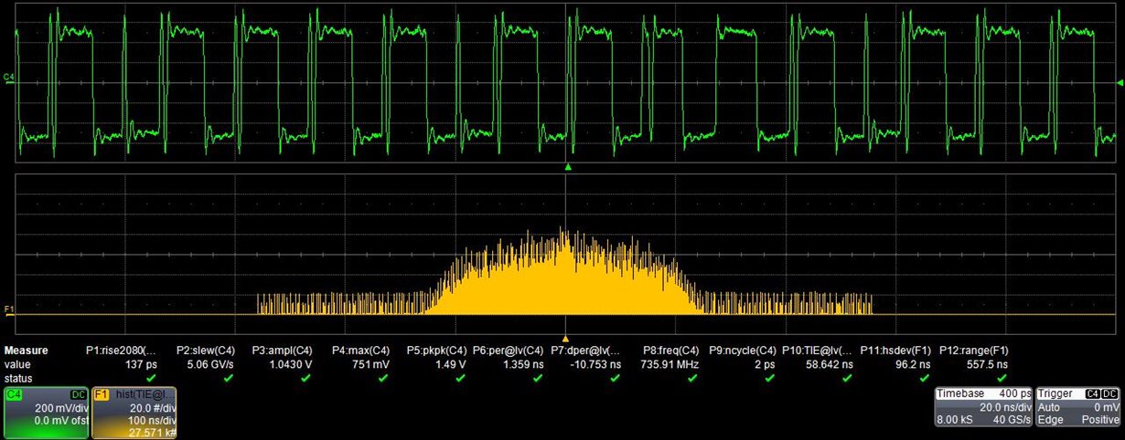
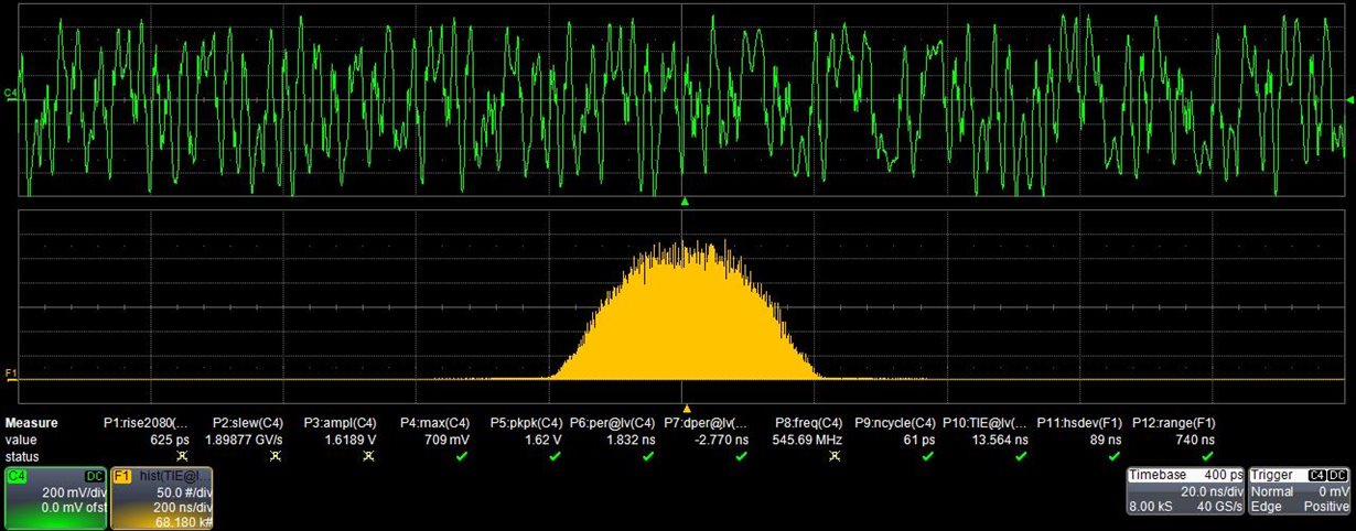
    I measured the waveform of input and output lane of the TMDS171,pinstrap mode

    1)EQ_SEL:NC(Adaptive EQ)

    2)PRE_SEL:NC(0dB)

    3)TX_TERM_CTL:NC(Auto select)

    The waveform of the input lane2 is shown as below

    The waveform of the output lane2 is shown as below

    There seemed to be much signal distortion issues about the output lane2 waveform,so I checked the PCB layout ,but I didn’t find any doubts.

    I change it to IIC mode, and I tried almost all configurations,I found that the waveform would be a little better if PRE_SEL was set to -2dB,and the TX_TERM_CTL was set to 150Ω~300Ω,but still be bad

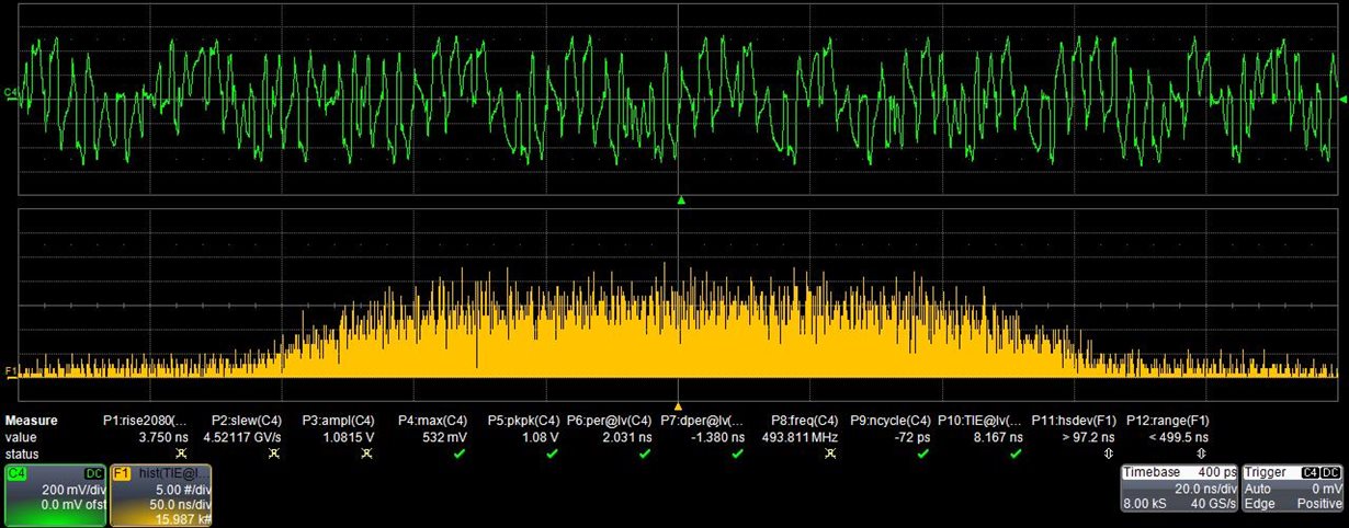
    I measured the output of TMDS141 on the Digilent Genesys EVM board,the waveform is shown as below

    clock

    data lane

    It seems to have the same problem as my board,I found that FPGA can't capture 1080P video neither on the Genesys EVM board occasionally. 

  • Can you share schematic and layout? Please accept my friend request and send it directly if it is sensitive to post on the forum.

    Regards,
    JMMN
  • I don't see any obvious issues from the shared schematic. Can you read back Page 1 (write 01h to address FFh), registers B0h and B1h?

    Thanks,
    JMMN
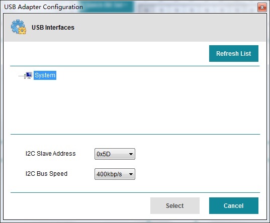
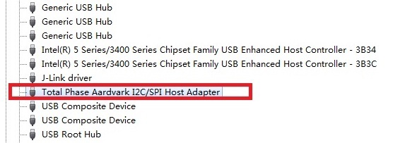
  • Eyescan Tool cannot find any TI's Interface

    TP240141 is connected to the computer,and the USB driver is installed already, TP240141 is recognized by Windows system.

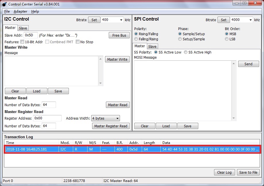
    if I use Control Center software designed by Total Phase,the register can be read successfully.

    I was totally confused...

  • The eye scan tool interfaces through USB to the I2C bus using a TUSB3410 (available on the TMDS181/171 EVMs), without a TUSB3410 the tool does not work.

    You can pull the register data using Total Phase Aardvark.

    Regards,

    JMMN

  • Page0 and Page 1 register of TMDS171 cannot be read by TP240141 mentioned on SLLU217A,just bacause TP240141 does't use TUSB3410

    so if I want to read the Page0 and Page1 register of TMDS171 on my board,I have to use TMDS171 EVM,and the I2C address of EMV board must be different from the board designed by myself.

    Is that correct?

  • Page 0 and Page 1 can be read by Total Phase Aardvark (TP240141) connected to the SDA_CTL / SCL_CTL lines of the TMDS171.

    or

    Page 0 and Page 1 can be read by Eye Scan Utility connected to a TUSB3410 connected to the SDA_CTL / SCL_CTL lines of the TMDS171.

    Both will work, and you can adjust the address of either utility to match the address of the TMDS171 being accessed.

    Regards,
    JMMN
  • Hi JMMN

    I readback regB0h and regB1h of Page1,but I'm not sure the operation is correct or not

    write_TMDS171(0xFF,0x01);//Page1

    read_TMDS171(0x00);//read


    the value is shown as below

    reg0xB0:0x5E

    reg0xB1:0x88

  • Ok, register B1 bit 7 = 1 means the clock is detected. Register B0 is is 0x5E means the detected clock rate is 150 MHz.
  • That is the clock rate I would expect for the 1080P mode. Can you try forcing it to redriver only mode and see if it performs better?
  • Hi,JMMN

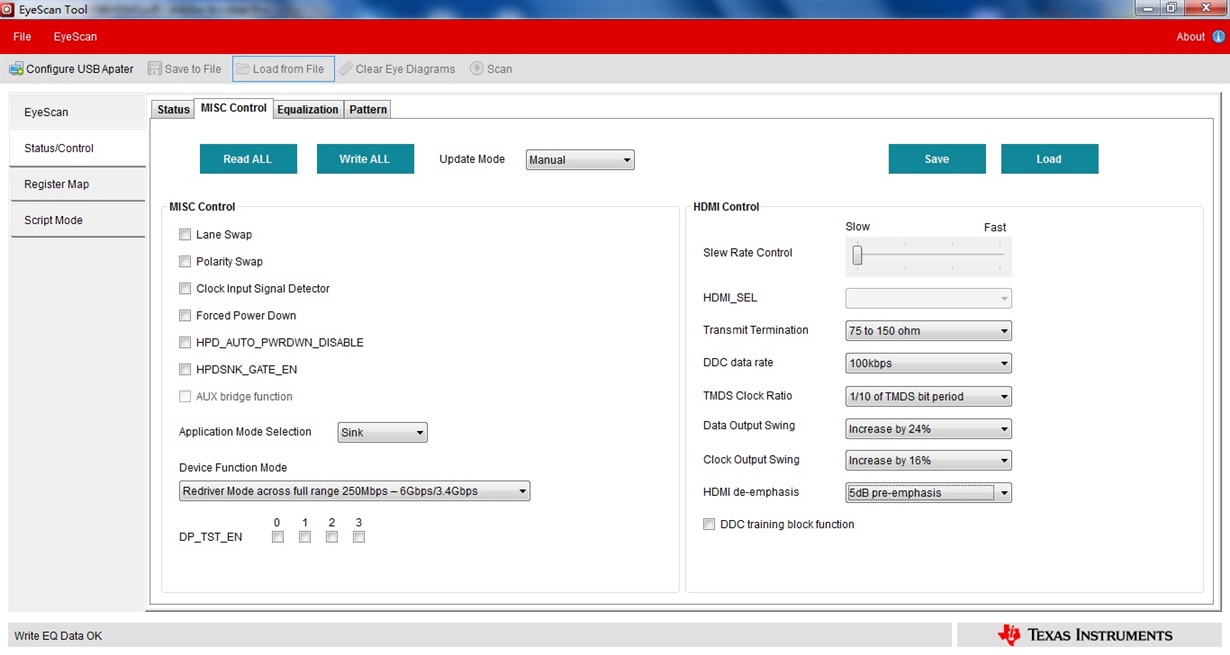
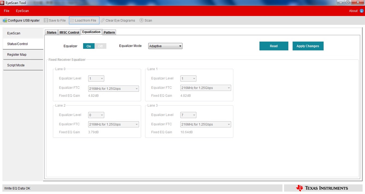
    I changed TMDS171 to TMDS181,and I force it to redriver mode,the other configuration is shown as below

    PRE_SEL:5dB

    TX_TERM:75~150

    AEQ

    Data swing increse 24%

    CLK swing increse 16%

    it works well,FPGA can capture 1080P60 data successfully.

    since I use a camera and splitter, so I change to the second port of the splitter,this time it does't work.

    I connect camera directly,it does't work neither

    I find another configuration for "second port" and "camera directly" situation,it seems to be better,but it does't work in "first port" situation

  • A few recommendations: tx terms of 75 to 150 are only used for 6G operation, you should use 150 to 300 ohms. 5 dB of de-emphasis is not recommended I would use 2 dB. Are the swing increases required to be very high? Typically, we would only use that high of a swing if driving a 10M + cable. Otherwise you may be overdriving the sink.

    If you swap to retime mode, you can use eye scan to see how clean the signal coming into the TMDS181 / 171 is.

    Regards,
    JMMN

  • Thank you for your help!

    The waveform of the TMDS181 output will be perfect when I removed FPGA from the board,with the 50ohm pull-up resistors leaving on the board.

    It seems that FPGA causes reflection, I just don't know why.
  • Are there series capacitors between the TMDS181 and the FPGA on the board? It may be that the swing of the TMDS181 is set too high for the system.
  • The output of the TMDS181 and FPGA is DC coupled.
    The resistor of VSADJ pin is 6.98K, once I changed it to 5.1K,the eye did't improve,I aslo changed it to 10K,this time the swing of the TMDS181 was about 500mV,but the issue remained.

    I will check it again and I will attempt to keep decreasing the swing by increasing the value of the VSADJ resistor.
  • I change the VSADJ resistor to 12K,and the swing of the TMDS181 will be about 500mV,but the issue remains